
3D-printed extensions such as scoops and ploughs make a great addition to Rovers in a sumo battle. It’s also a good introduction to Computer-Aided Design (CAD) and 3D printing.
This activity explores how to design extensions that attach to the Rover Bolt Clip Adapter. The clip adapter can be purchased from the Micromelon store, or the files can be downloaded from Printables or Thingiverse.
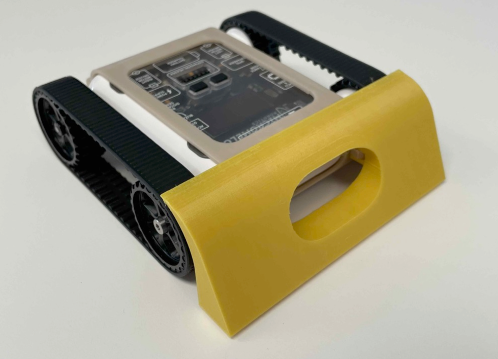
Example sumo attachment fitted to the Rover
For an introduction to sumo, see the activity guide:
Setup
You’ll need:
- 2× M3 bolts to attach the extension to the Rover.
- A Rover Bolt Clip Adapter.
- A piece of paper and a pen for initial sketches before transferring to CAD.
- A computer with CAD software. TinkerCAD, Onshape, and Autodesk Fusion 360 are all excellent options with free versions available.
Familiarity with CAD is helpful but optional.
Our Approach
Stage 1: Sketch on Paper
Designing your extensions on paper before transferring to CAD is important. Start by drawing some rough sketches of your ideas. Once you have a few you like, draw the side profiles for each.
The side view is the most important, it forms the basis of the CAD model. Remember to add holes where bolts can pass through and connect to the bolt clip adapter. You’ll also need to consider a cut-out for the ultrasonic sensor on the front face.
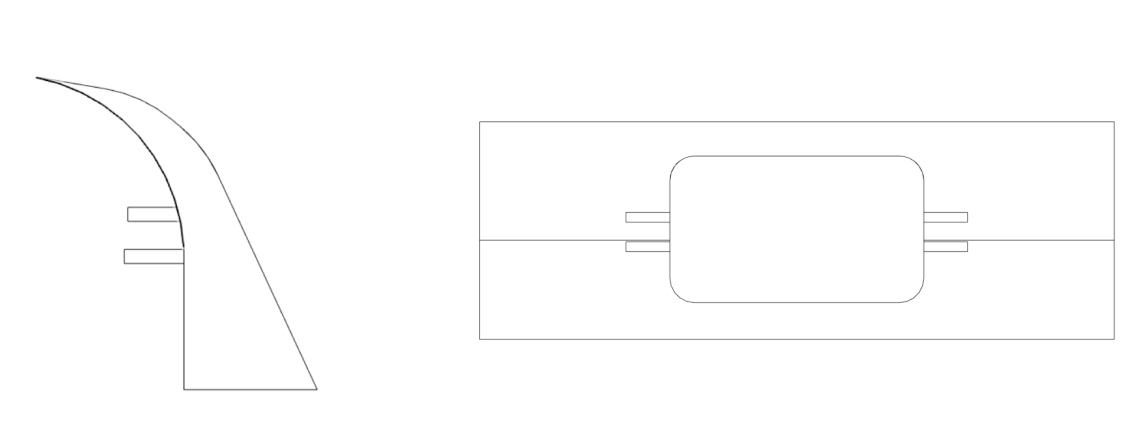
Example side profiles of a sumo attachment
Stage 2: Transfer to CAD

Dimensions for the example attachment
Once you’re happy with your sketch, transfer your design into CAD and dimension your part accordingly. Note that the dimensions of your 3D-printed piece will differ slightly from the CAD due to 3D printing inaccuracies.
The dimensions for the example sumo ramp scoop above can be helpful when designing the portion of the attachment that connects to the bolt clip adapter.
Stage 3: Print and Iterate
Once you’ve printed your extension, see if it fits on the Rover Bolt Clip Adapter. It may not fit perfectly first go, correcting issues may take a few redesigns. You can also try experimenting with different print infills to see how they affect the strength and rigidity of the part.
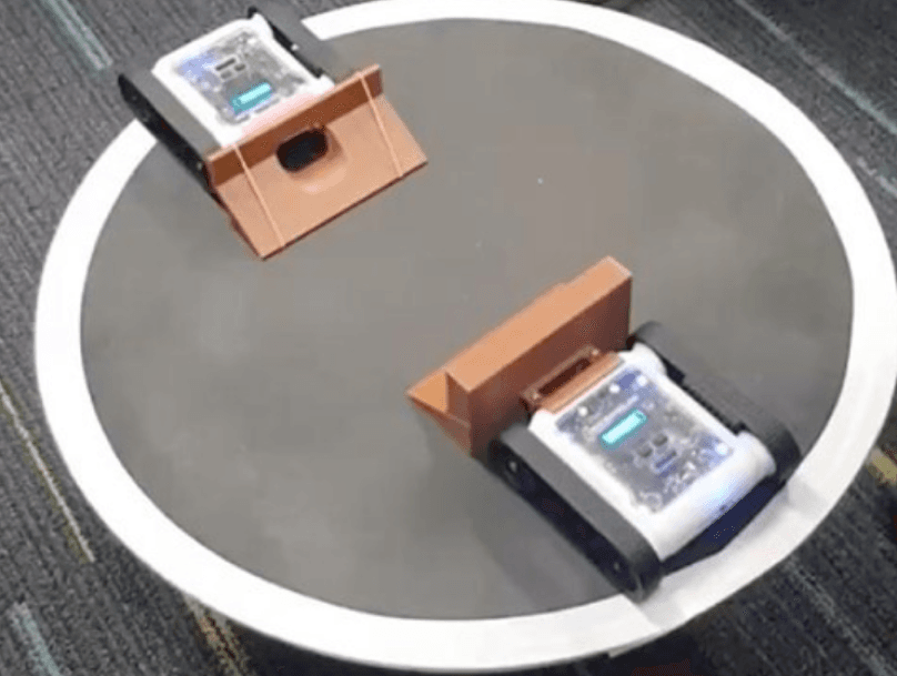
Once your attachment is fitted and ready, put it to the test in a sumo match.