The gyroscope is one of the five sensor types on the Micromelon Rover. It’s a component built into the Rover’s PCB (printed circuit board), only about 2.5 mm × 3.0 mm wide and 0.83 mm tall. The same component also includes another sensor: the accelerometer.
What Does It Do
The gyroscope detects how fast the Rover is rotating and in what direction it is rotating. It’s the key tool for understanding the Rover’s rotational movement, think of it as the Rover’s sense of direction.
History of the Gyroscope
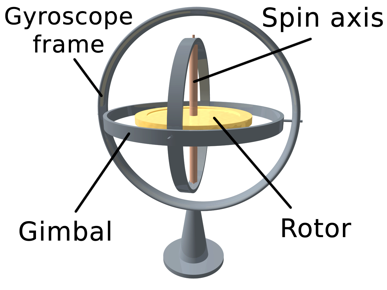
A traditional mechanical gyroscope with gimbal rings and a rotor
Gyroscopes have existed long before digital devices like the Rover used them, they’ve been used as tools since the 1800s. Traditional gyroscopes are built out of metal loops called gimbal rings that can spin freely, attached to a central piece called the rotor.
The spin axis and rotor are designed to spin at a high speed. As they spin, the attached gimbal rings rotate inside the gyroscope frame. The mechanics are easier to see in motion than to describe, the videos below show a traditional gyroscope when it is and isn’t in motion.
Gyroscope in motion, angular momentum keeps it upright
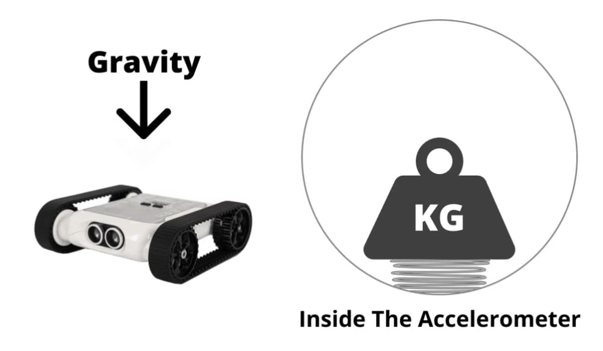
When the gyroscope’s components are spinning, it remains stable, seemingly against the force of gravity. This is due to a phenomenon called angular momentum: while the spin axis and rotor are spinning fast enough, angular momentum is maintained and the gyroscope keeps its vertical position against gravity. (Footage above sourced from the YouTube channel ScienceOnline.)
How Does the Rover Gyroscope Work?
The gyroscope on the Rover is a MEMS (microelectromechanical system) gyroscope, which mechanically works very differently from a traditional mechanical gyroscope, there’s no spinning rotor or gimbal rings. The fundamental physics is the same, but the engineering is more complicated than we’ll cover here.
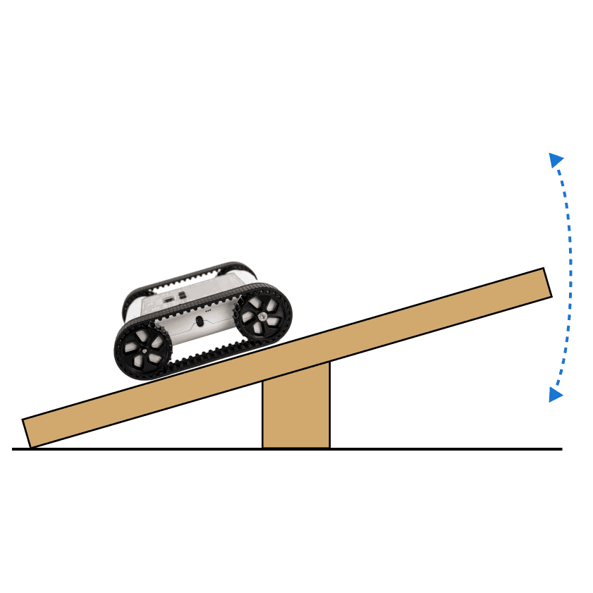
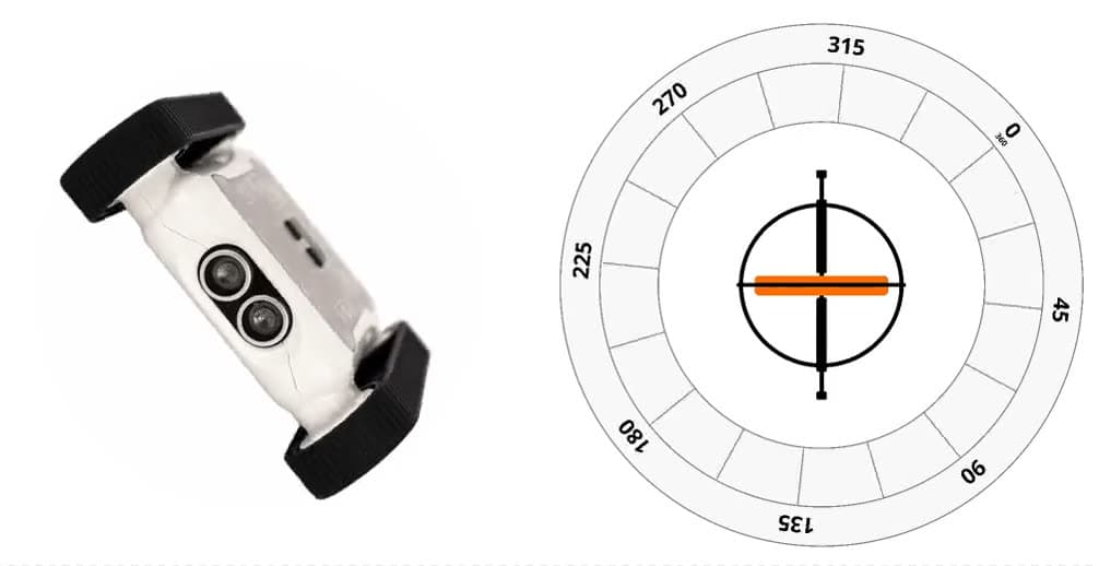
To simplify, imagine that inside the Rover there’s a traditional mechanical gyroscope that is constantly in motion (so it always stays straight against gravity). Around the gyroscope is a protractor. When the Rover is flat on the ground, the protractor aligns the gyroscope with 0°.
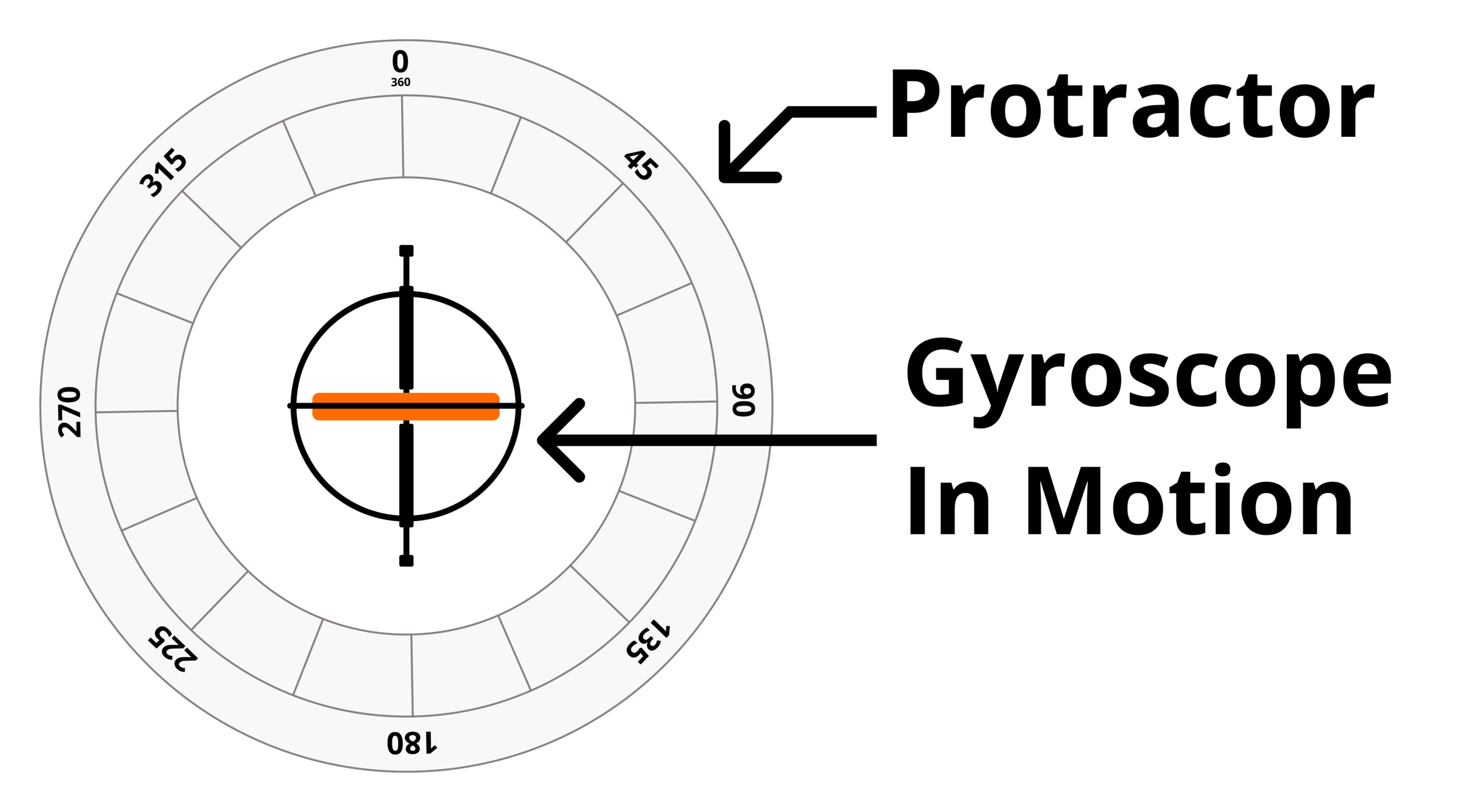
Simplified Rover gyroscope, gyroscope inside a protractor
- The Rover starts flat. The 0° mark of the protractor is aligned with the gyroscope, there’s no rotation.
- As the Rover rotates, the protractor rotates with it. The gyroscope remains stable and straight.
- When the Rover stops rotating, the gyroscope now points at a different degree of the protractor.
The Rover determines degrees of rotation based on how the protractor rotates around the gyroscope. The Rover could also rotate backwards/forwards or spin on the spot, to keep things clear we use the three axes of movement.
The Three Axes of Movement
Using the gyroscope, the Rover can detect that it’s rotating, and can also tell you specifically in which direction it’s rotating.
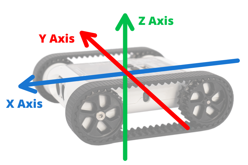
The X, Y, and Z axes on the Rover
- X axis runs from back to front of the Rover.
- Y axis runs across the Rover middle from left to right.
- Z axis runs up and down through the Rover.
The Rover can rotate around all three axes. Below are demonstrations of rotation along each axis.
X-axis rotation
Gyroscope Calibration
Although the Rover’s gyroscope is reliable at detecting rotation changes consistently, it won’t always be perfectly accurate. Even when the Rover is completely stationary, the gyroscope may report the slightest amount of rotation. The difference between the gyroscope value and the real rotation is small enough that, in 99% of circumstances, it’ll be inconsequential when programming.
This irregularity is unavoidable for the built-in gyroscope, but you can re-calibrate the Rover’s sensors if you want to make them as accurate as possible.
How to Recalibrate the Gyroscope
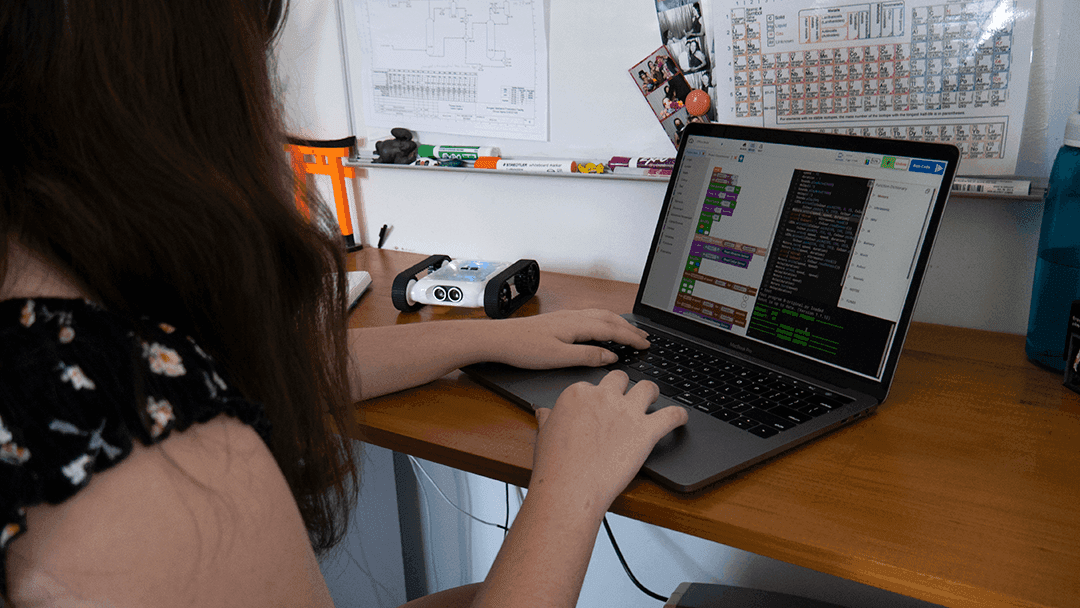
Recalibrating the gyroscope from the Code Editor
- Open the Code Editor and connect to the Rover you want to calibrate.
- In the Code Editor’s program menu, click the Rover button to open the dropdown.
- Select Sensor Calibration.
- Place the Rover on the most level surface possible (as the dialog instructs).
- Press Calibrate.
Your Rover should now be calibrated.
Programming the Gyroscope
Open the Code Editor, connect to a Micromelon Rover, and open Sensor View. Click the ROVER button next to your Rover’s name to open it.
In the Sensor View dialog, the gyroscope values are in the bottom-right table. The second column is the gyroscope values, and the third column is the accumulated gyroscope values. Move the Rover around and watch how the X, Y, and Z values change.
Opening Sensor View in the Code Editor
Gyroscope vs Accumulated Gyroscope
Gyroscope value
The values in the gyroscope column are degrees per second (dps). While the Rover isn’t rotating, the dps value will be roughly 0. If you rotate the Rover on the Z axis at 90 dps, it will take 4 seconds for the Rover to complete a full 360° spin.
Accumulated gyroscope value
The values in the accumulated gyroscope column are accumulated degrees. When you first open Sensor View or run code, the accumulated values are set to 0. As the Rover rotates anticlockwise, the accumulated degrees increase. If you rotate the Rover 360° on the Z axis, the Z value will be 360. Rotate another 180° and the Z value will be 540. The accumulated degrees keep increasing as you rotate. If you rotate in the opposite direction, the degrees decrease.
Which one is better?
Both are useful in different circumstances, depending on the challenge, you may need to use one or both. We’ll cover two coding examples below.
Negative values
We know there are three axes the Rover can rotate around, but should you rotate clockwise or anticlockwise around the axis? The answer is both. Negative values are clockwise rotation; positive values are anticlockwise rotation.
Using the Gyroscope Value in Code
Let’s write a simple program to make the Rover make sounds when it rotates. The faster it rotates, the higher the pitch.
Building the gyroscope-controlled buzzer program
- Start with a While True loop, the program needs to repeat to keep getting live data.
- Create a variable from the Variables category. Call it
gyro. - Set the
gyrovariable to a Read From Gyroscope block. Change the dropdown to Z Axis (in the Sensors category. Python:IMU.readGyro(2)). - The Rover’s buzzer can’t use negative numbers, so check if the Z-axis gyroscope value is negative. Use an IF block, in the condition, check if
gyrois less than 0. - Inside the IF block, when the condition succeeds, update
gyrotogyro × −1using a multiplication block. This ensuresgyrois always positive. - Drag out a Play Sound at Hz block from the Lights/Sounds category. Inside it, place
gyro × 10using another multiplication block, multiplying by 10 makes the sound more pronounced. - Press Play.
While running, the Rover makes sound depending on how much it’s rotating around the Z axis. The faster you rotate, the higher the pitch. Give the Rover a spin (carefully).
Using the Accumulated Gyroscope Value in Code
Let’s write a similar program using the accumulated gyroscope value.
Building the accumulated-gyroscope buzzer program
- Start with a While True loop.
- Create a variable called
gyro. - Set
gyroto a Read From Accumulated Gyroscope block, with the dropdown set to Z Axis (Python:IMU.readGyroAccum(2)). - Use an IF block to check if
gyrois less than 0, and if so multiply it by −1 to keep it positive. - Drag out a Play Sound at Hz block and place
gyroinside (no multiplication needed, these numbers are larger than the per-second values). - Press Play.
While running, the Rover makes sound as you rotate it on the Z axis. As you rotate in one direction the sound increases; rotating back the other way winds it down again.
Wrapping Up
Now that you’re familiar with the gyroscope, how it works, and how to program it, try one of the activities below.