When creating objects for 3D printing, it’s sometimes hard to print the entire object at once, it helps to break it up into smaller pieces and put them together. Gluing pieces together can be tedious, and challenging when you want to replace parts. So how can we 3D-print our own connections? This guide lists a few options.
Joints
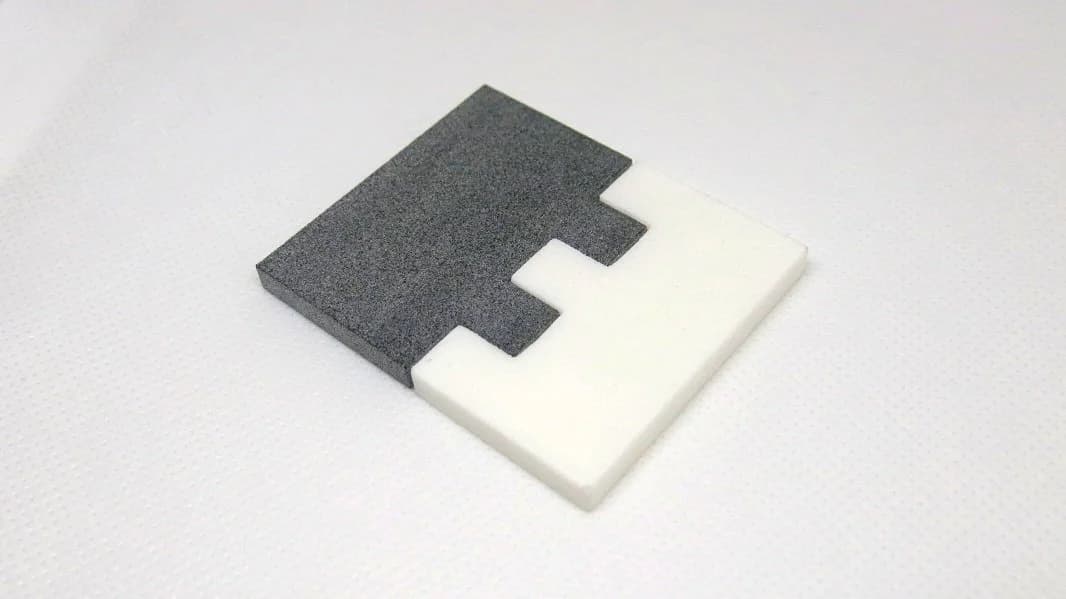
Simple shape joints can be made by 3D-printing male-to-female connectors. You can find inspiration from woodworking joinery such as dovetails. Connecting these is as simple as snapping the two parts together, friction holds the joint.
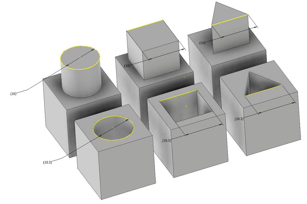
3D-printed shape joints
It’s important to remember that printers don’t print dimensions perfectly, so it helps to add a bit of tolerance, make the female connector slightly larger than the male connector. This is a trial-and-error process as each printer is different. In our experience, +0.3 mm for a hole is a good starting point.
Pros: Simple to design, easy to print, easy to assemble.
Cons: Somewhat breakable, lots of trial and error, weak connection.
Self-Tapping Screw Holes
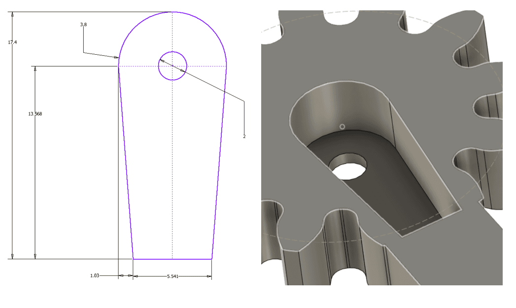
Adding appropriately sized holes to your design lets you add screws that self-tap as they’re screwed in. While normal circular holes work, a great way to implement self-tapping holes is to use the following design:
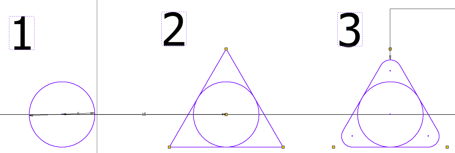
Self-tapping hole geometry, circle with tangential triangle and fillet
- Create a circle the same size as your screw (adjust this dimension depending on your printer).
- Create a triangle with lines tangential to the circle.
- Apply a slight fillet to the triangle.
Self-tapping hole printed and ready
Once these holes are printed, screw a screw all the way in, this applies thread to the inside of the hole. If the screw feels loose, make the dimension of the circle in step 1 a bit smaller.
Pros: Simple to design, easy to assemble, easy to print.
Cons: Requires the purchase of screws, weak connection.
Threaded Inserts
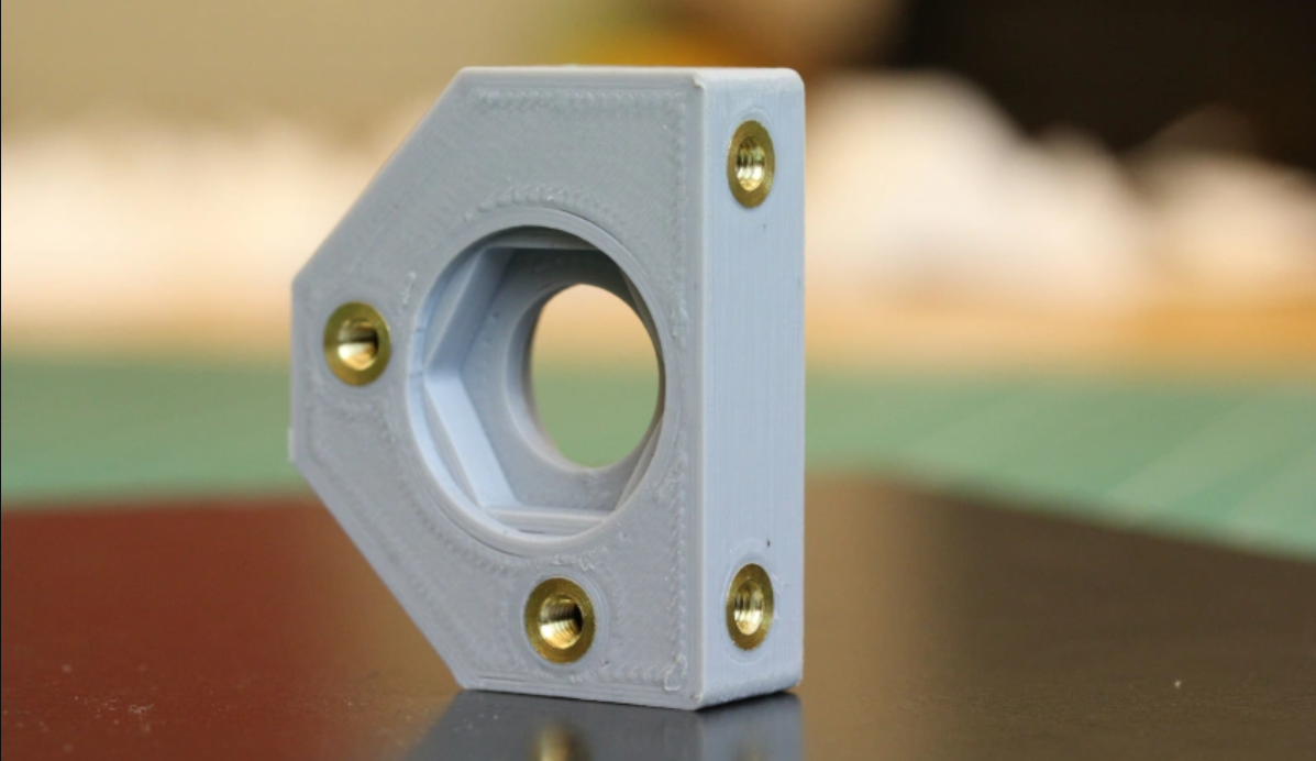
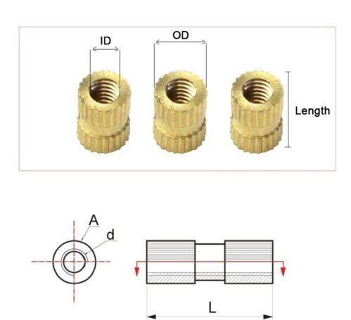
Heat-set brass insert in a 3D-printed hole (Credit: Joshua Vasquez, Threading 3D Printed Parts: How to Use Heat-Set Inserts)
Threaded inserts are the step up from self-tapping screw holes, a great way to add strong metal threads to screw holes in 3D prints. Buy threaded brass inserts for your desired screw size, then heat them and gently press them into a corresponding hole in your print. Once flush with the surface, the insert cools and stays in place.
For a more extensive guide on heat-set inserts, see Joshua Vasquez’s Hackaday article. Below is the basic technique:
Setting a brass insert with a soldering iron
- Purchase threaded inserts for the desired screw size (ID). Note the outer diameter (OD) of the insert (not the screw size).
- When designing, create the holes the same size as the insert OD, and make the depth of the hole 1.5× the length of the insert.
- Hold an insert on the mouth of the printed hole using pliers.
- Gently rest a soldering iron (matched to the material’s melting range) on the insert and slowly push it into the hole once it’s hot.
- When about 0.5 mm of the insert is left to push in, remove the soldering iron and use a flat piece of metal to press it the rest of the way.
- Once flush with the printed surface, hold until the plastic and insert cool.
Pros: Simple to design, very strong connection, easy to assemble, easy to print.
Cons: Requires purchase of brass inserts and screws, can be time-consuming.
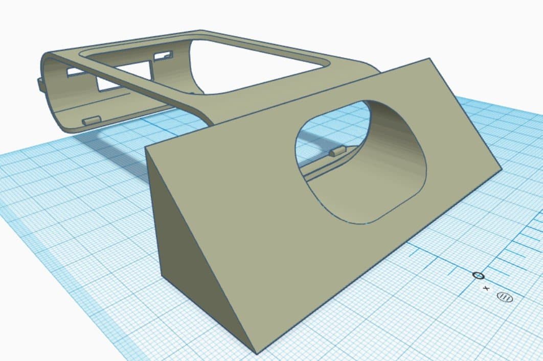
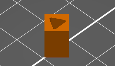
Print-In-Place
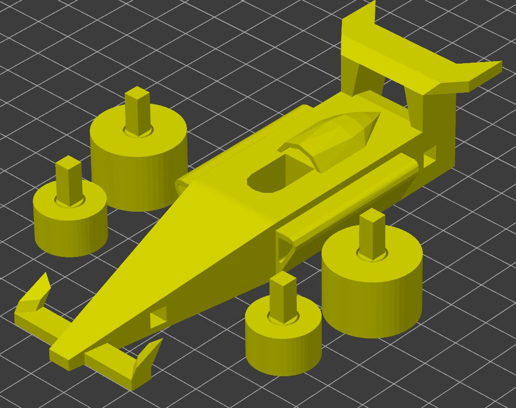
Print-in-place race car with rotating wheels
Print-in-place is a technique for designing objects with moving components that don’t require additional assembly. The idea is to design a single object in two unconnected, free-standing parts. If designed correctly, the part holds together even when taken off the build plate. In the design above, the four wheels are printed with axles and rotate about the axle without assembly.
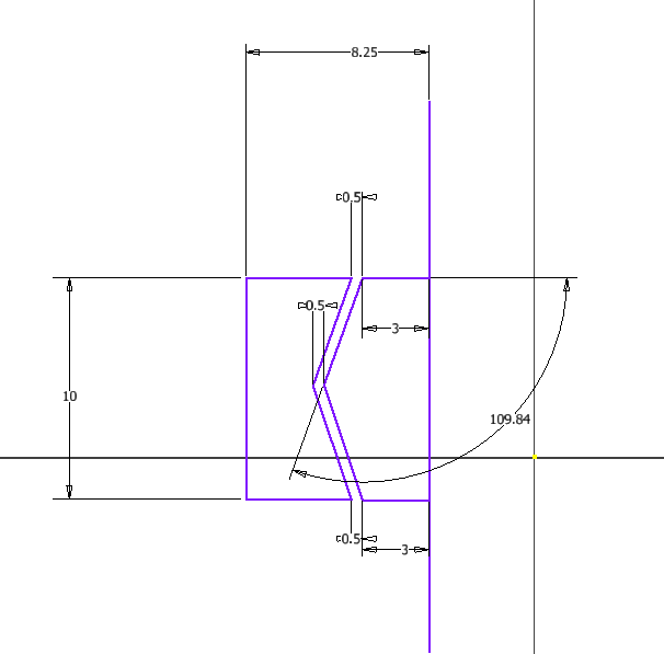
Cross-section sketch of the wheel-on-axle design
The axle inside isn’t actually touching the inner surface of the wheel, the printer can print the axle and wheel without support. The angle between the axle and the wheel stops the wheel slipping off.
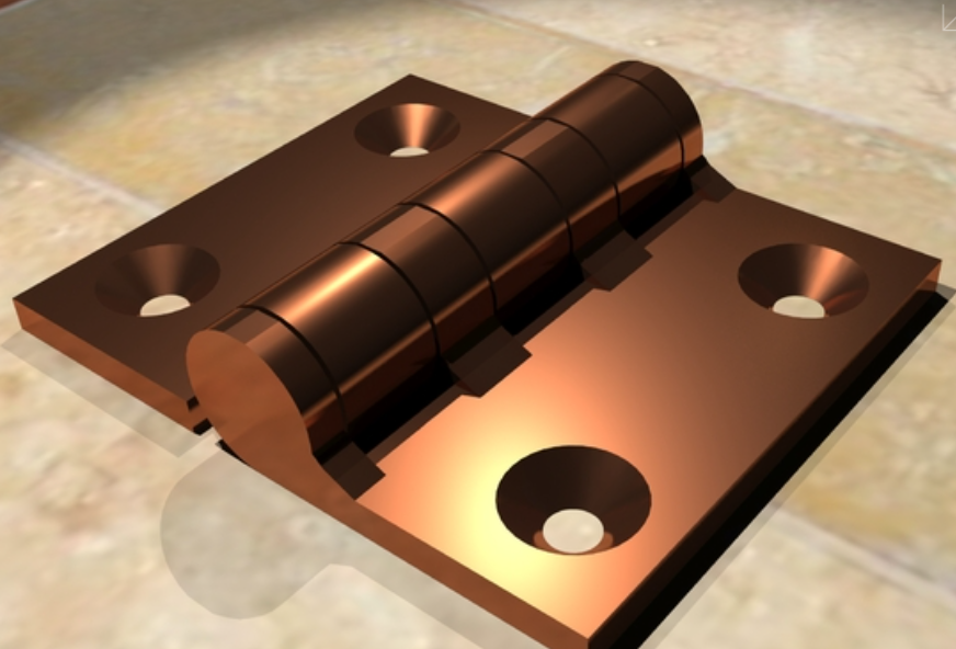
Print-in-place hinge
The hinge above uses a technique similar to the race-car wheels, but is printed in a different orientation. There are many other variants of print-in-place joints, but they can be very complex to design.
Pros: No assembly required.
Cons: Difficult to design, difficult to print, joints can be breakable.