Rover attachments are a great way to extend the Rover’s capabilities with 3D printing. It’s a wonderful way to upgrade or customise your Rover to suit any project imaginable.
Existing Attachments
We’ve made a few attachments for you to use or take inspiration from. These fit onto the mounting tabs on the Rover body and use the sensors and servos to transform the Rover into things like diggers, tippers, or claws.
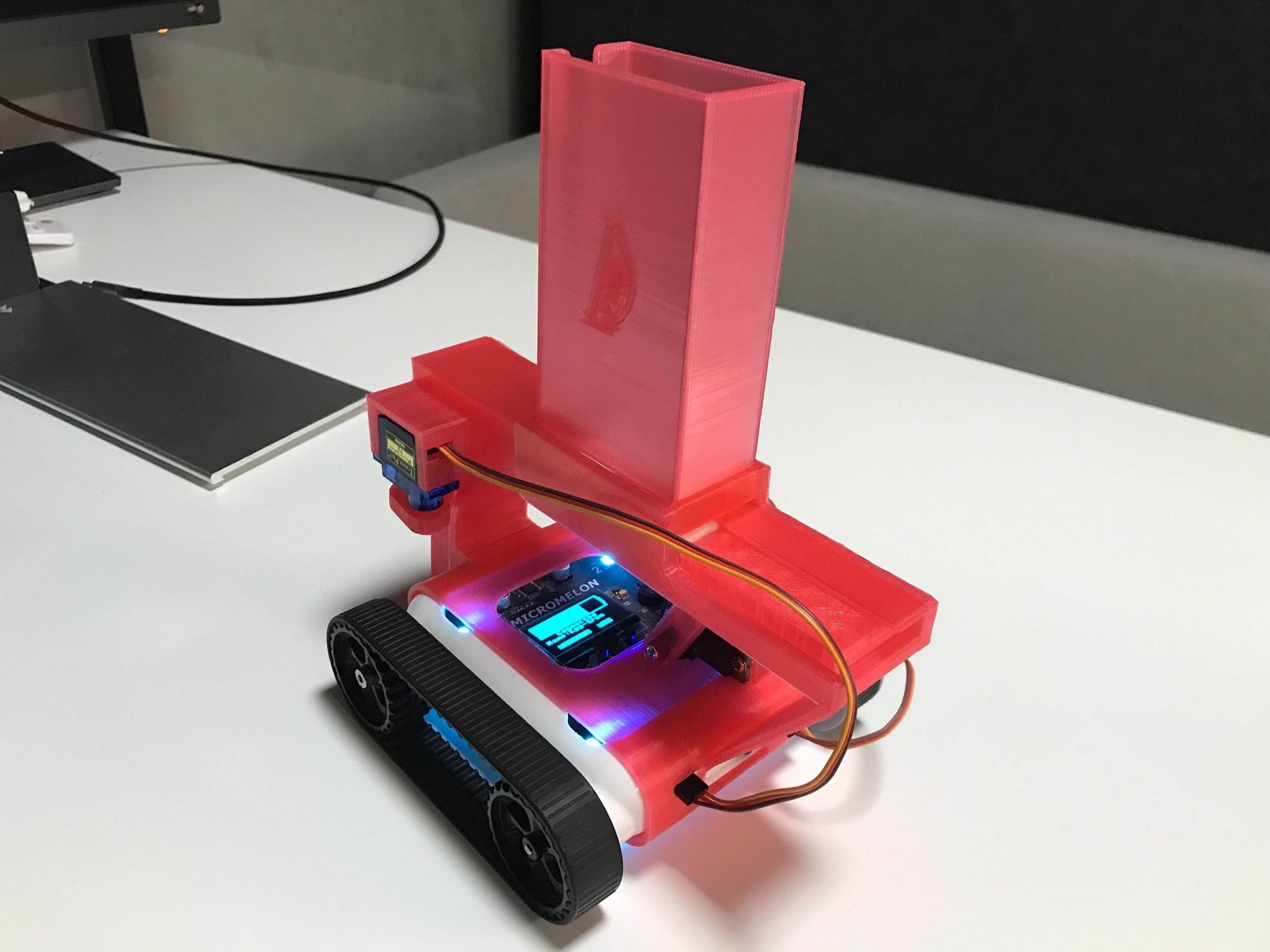
Domino Layer
For more on our existing attachments, see the Rover Expansions & 3D Printing page.
Constraints
It’s good to be aware of what the Rover can do before designing an attachment.
Sensors
It’s helpful to use the existing sensors on the Rover (like the ultrasonic sensor). When using these, your attachment must not hinder their operation, for example, don’t cover the ultrasonic. An attachment could also be designed to hold an Arduino to serve as an expansion board for additional sensors.
Actuators and Power
The Rover has two servo ports at the back, so you’re limited to a maximum of two servos without further modifications. There’s also a limit to the power the Rover can output, when using a servo expander over I2C, the Rover may struggle to power many actuators simultaneously. The attachment must also not be too heavy; the Rover motors can’t handle a significant weight increase without a drop in speed.
How to Get Started
Before starting, it’s a good idea to have some practice in 3D-design software such as Fusion 360, some of these designs can get complex.
- Consider your design and allocate the servos. Because of the two-servo limit, moving components on the attachment must be considered carefully.
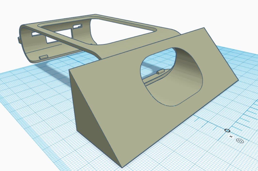
- Download the basic Rover shell: Basic Shell (STP).
- Build up from the Rover shell. Start with where the servos are going to sit. Finish all your static components before moving on to the moving pieces. Think about how many parts your attachment will be made of, one part, or an assembly?
Tips and Tricks
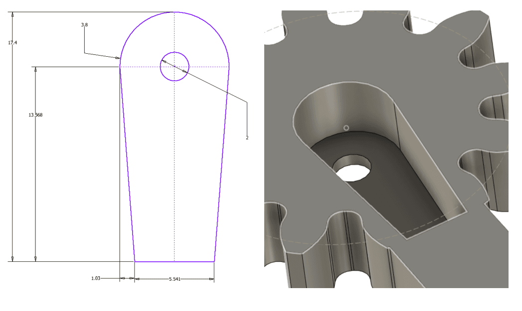
Component Sketches
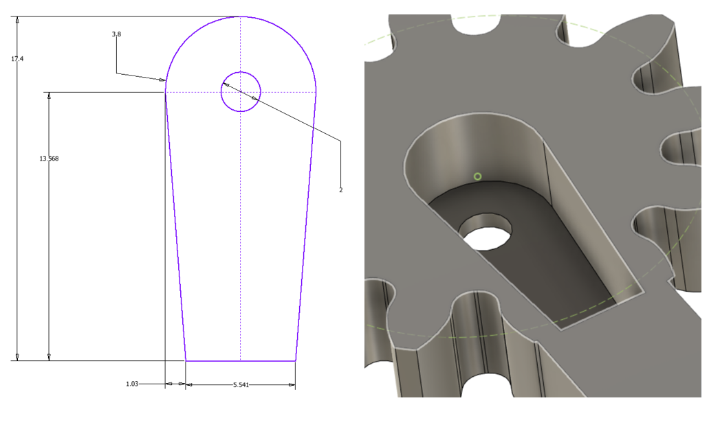
Servo Horn Sketch, extrude about 5 mm in
Sketches and components above can be used as starting points in your designs.
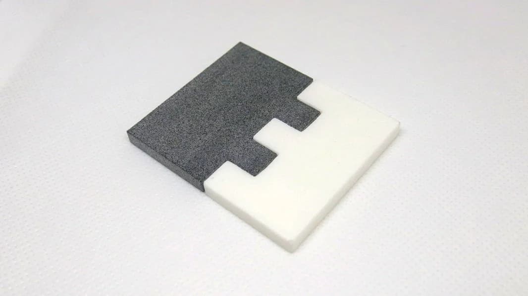
Connections
When printing your design, break the attachment into smaller, easy-to-print parts, this gives a robust, high-quality result that can be quickly prototyped. The connections between these parts must be considered carefully. See the connections guide for techniques that suit your design.
Gears
While designs are limited to two servos, the output of these actuators can be modified to suit your needs. The half-rotation range of a standard servo can be increased through gears, and rotational movement can be converted to linear motion using a rack-and-pinion system. For more, see the gears guide.