Designing 3D-printed attachments for the Micromelon Rover is a great way to upskill in CAD design while making your own custom additions. Tinkercad is a free piece of software that lets you bend and stretch existing shapes to create your own. In this guide we’ll go through some of the basic Tinkercad tools and how to design a sumo ramp for the Rover.
The Workspace
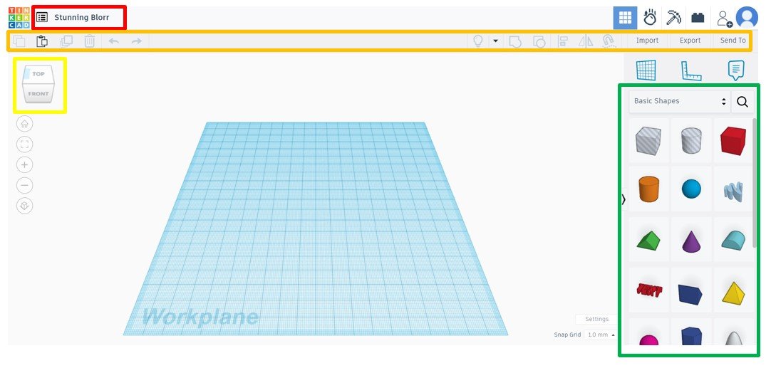
When a new project is opened in Tinkercad, the following screen is what we see. Highlighted by coloured squares are some important tools to get started.
- Red - This is the part name, simply click the word and type in your part name.
- Orange - This is where some of your keyboard tools are, such as ‘delete’, ‘copy’, ‘paste’, merge, etc.
- Yellow - This is the navigation cube, it can be clicked and dragged around to look at the part in 3D. Faces on this cube can be clicked to look at the front, top, and other faces.
- Green - This is where all of the starting shapes are, click and drag any of these onto the workplane to start modelling.
Key Tools
Measure tool: like a special ruler that shows how long an object is on all sides. It also shows the distance from the object to the ruler using green arrows. Click any number to change it and modify the shape. We recommend always having a ruler in the workplane.
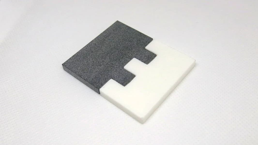
Holes and solids: the two types of object in Tinkercad. Grouping two solids together merges them into one solid. Grouping a solid and a hole subtracts the hole from the solid wherever they overlap. Ungrouping reverses the process.
Align tool: quickly aligns multiple objects to the same line. Very useful for making sure objects sit on the centre line of another object.
Designing a Rover Ramp
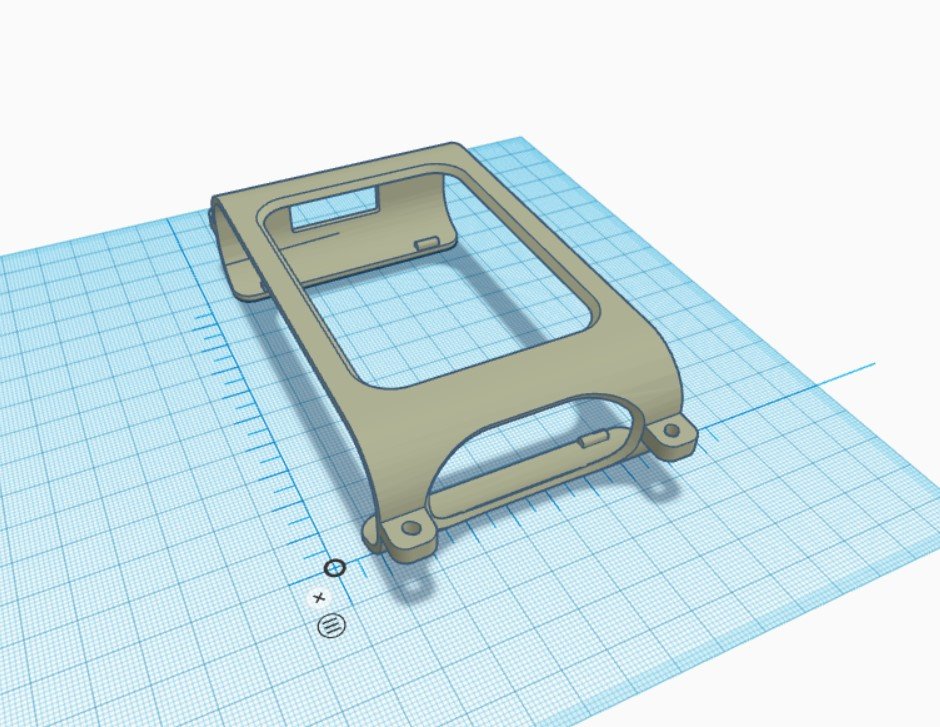
To get started, first download the rover shell clip. Next, open up the downloaded file in a new Tinkercad project by using Import > Choose a File > (open the file) > Import. Drop a ruler into the workplane and rotate the clip so that it looks like the image.
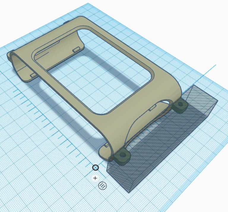
Use a rectangle set as a hole to cut off the bolt tabs at the front of the clip. Position the hole shape so it overlaps the tabs as shown, then group the objects together.
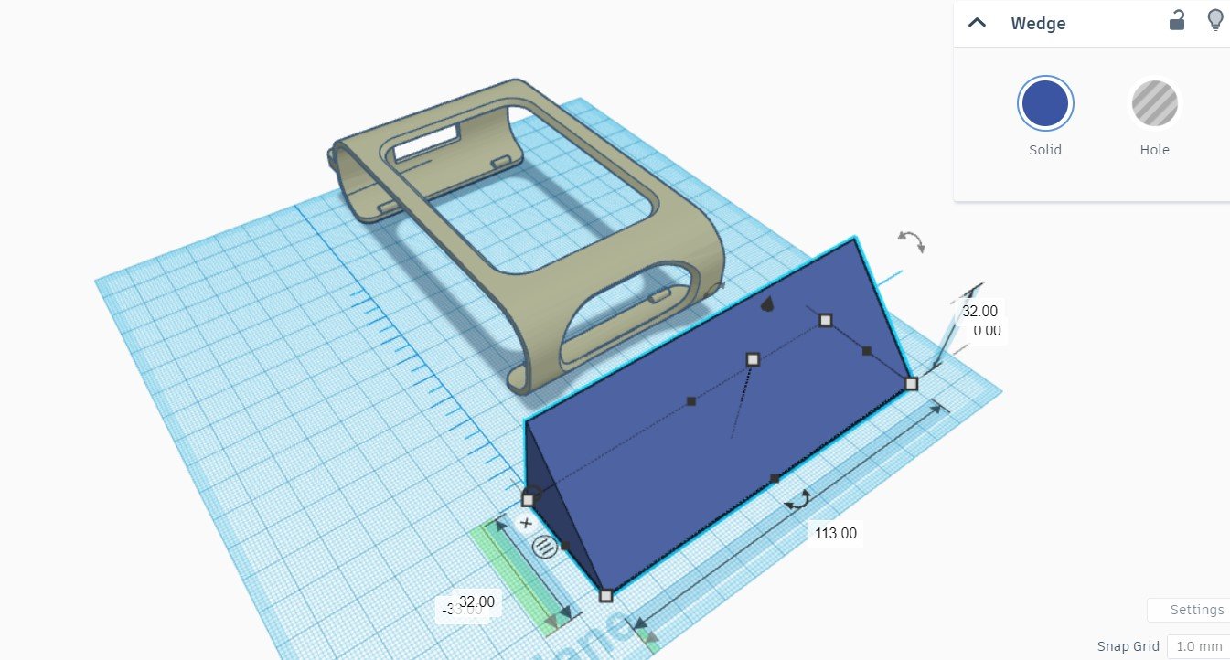
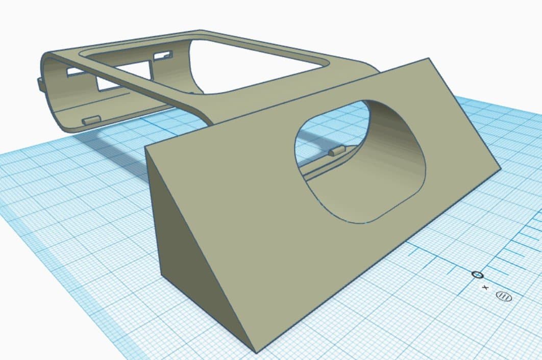
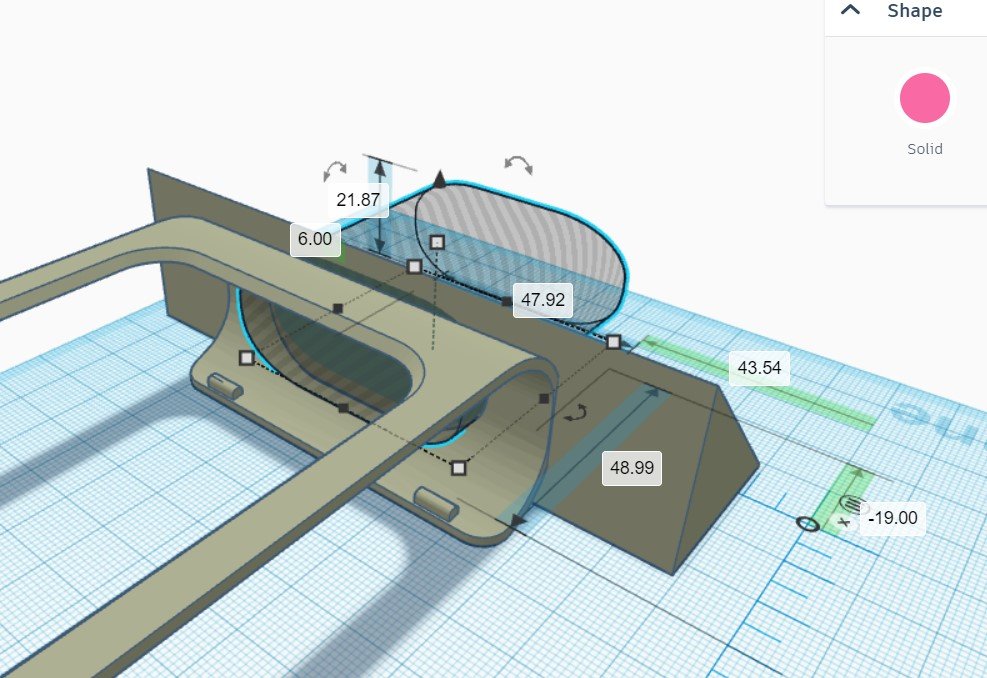
Now we need to make the weapon for our attachment. Drag a wedge onto the workplane and modify the shape so it serves as a sumo ramp. Use the measure tool to set the dimensions. It’s not attached to the clip just yet.
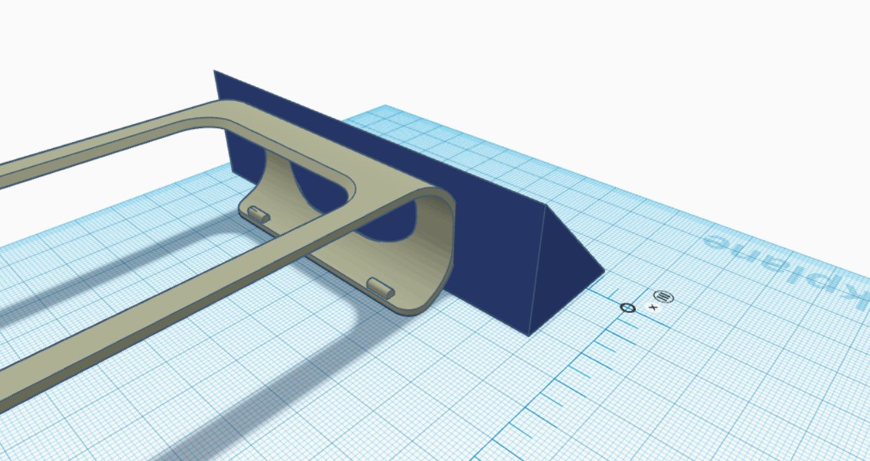
Move the ramp in so that it’s overlapping with the clip. Make sure it doesn’t come too far in as the rover needs to sit inside the clip. Use the align tool to make sure the ramp is centred on the clip. Don’t worry about the ultrasonic sensor opening, we’ll take care of this in the next step. Group the objects together once everything is in place.
Positioning the ultrasonic bore
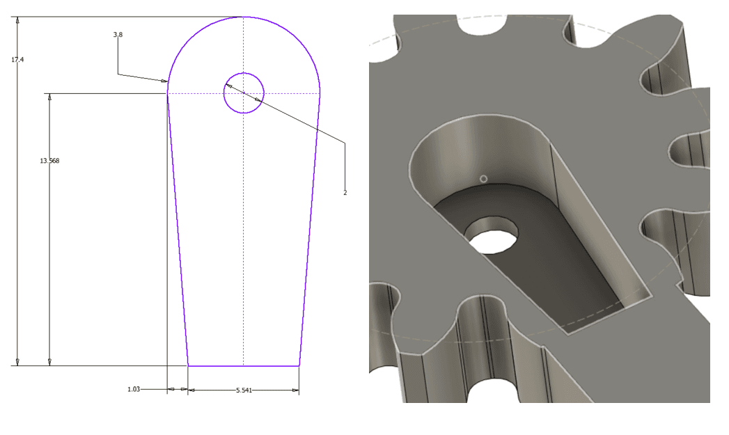
Download the Ultrasonic Bore and import it into the workplane. Position the bore as a hole so that it can cut through the hole on the clip and into the wedge. It’s easier to look from the back of the clip. The align tool and looking from many directions can help a lot with this step. Once everything is in position, merge the objects so the hole cuts through.
You’re Done!
Now that is the complete design on how to make a very basic attachment for the rover. Try experimenting with more complex shapes using a combination of solids. Maybe try to increase the amount of contact your shapes have with the rover clip to make a stronger bond.