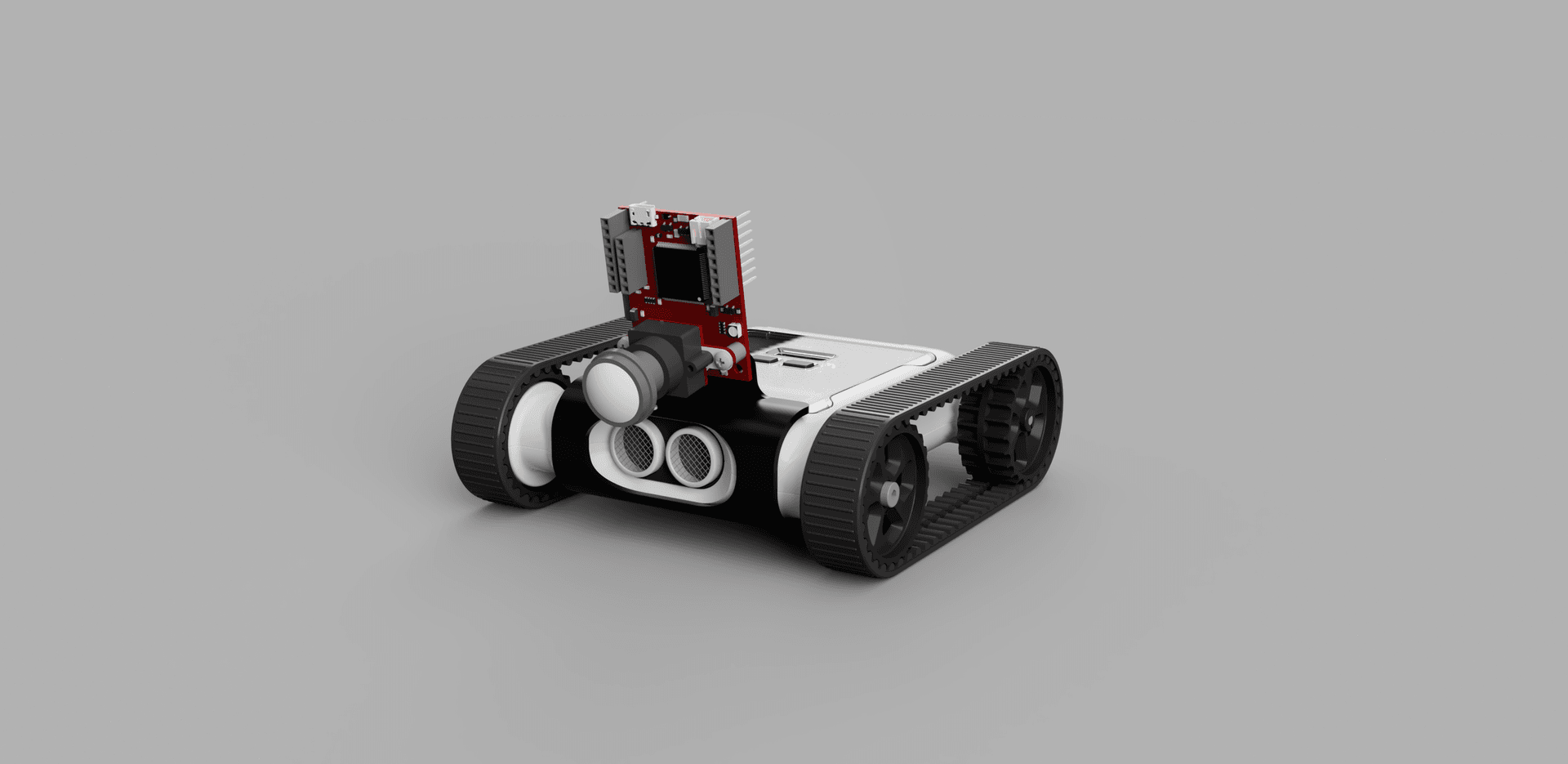
UART (Universal Asynchronous Receiver Transmitter) is a hardware communication protocol used between two devices. The Micromelon Rover features an expansion header that can be used to connect external devices like an Arduino or an IR sensor. This guide explains how UART works, how it’s implemented on the Rover, and how to connect a device using UART.
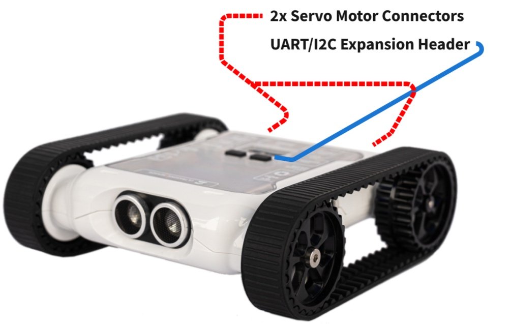
Rover expansion header where UART is exposed
What is UART?
The UART communication protocol is used to transmit data packets over two wires, it’s useful because it allows serial data to be transmitted from one device to another. UART is asynchronous, meaning no clock is needed to send data. All that’s required is the transmit pin of one device connected to the receive pin of another.
Since there’s no clock, the transmitter and receiver must agree on a predetermined transmission rate called the baud rate. UART also has a standard packet structure so the receiving device knows when to read the bits:
| Start bit | Data frame | Parity bit | Stop bits |
|---|---|---|---|
| 1 bit | 5–9 data bits | 0–1 parity bit | 1–2 stop bits |
- The start bit is held high until data is ready to be sent and then set low, this tells the receiving UART to begin reading the transmission line.
- The data frame contains the actual data and can be anywhere from 5 to 9 bits long, depending on whether the parity bit is used.
- The parity bit verifies the data, it counts the number of
1bits and sets the parity bit to 0 if the total is odd or 1 if it’s even. This ensures no bits have been changed during transfer. - The stop bit signals the end of a packet by pulling the transmission line to a high voltage. The receiver then stops reading.
Hardware Setup
UART wiring, RX to TX, TX to RX, plus shared ground
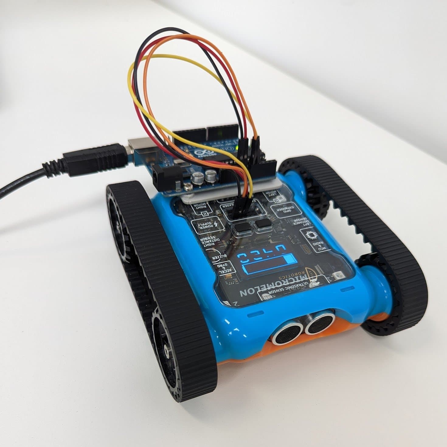
Connecting two devices using UART requires two wires. Each device’s RX (receive) pin must be connected to the other’s TX (transmit) pin. A shared ground is also needed between both devices.
The UART pins are on the expansion header below the LCD screen on the Rover. The 3.3V and GND pins are also required to power the device communicating with the Rover. Jumper wires can be used.
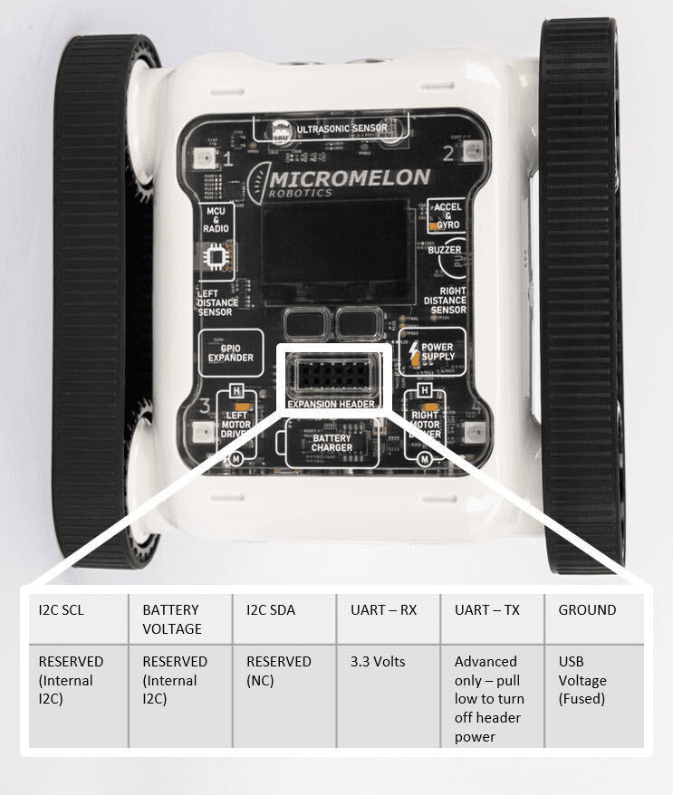
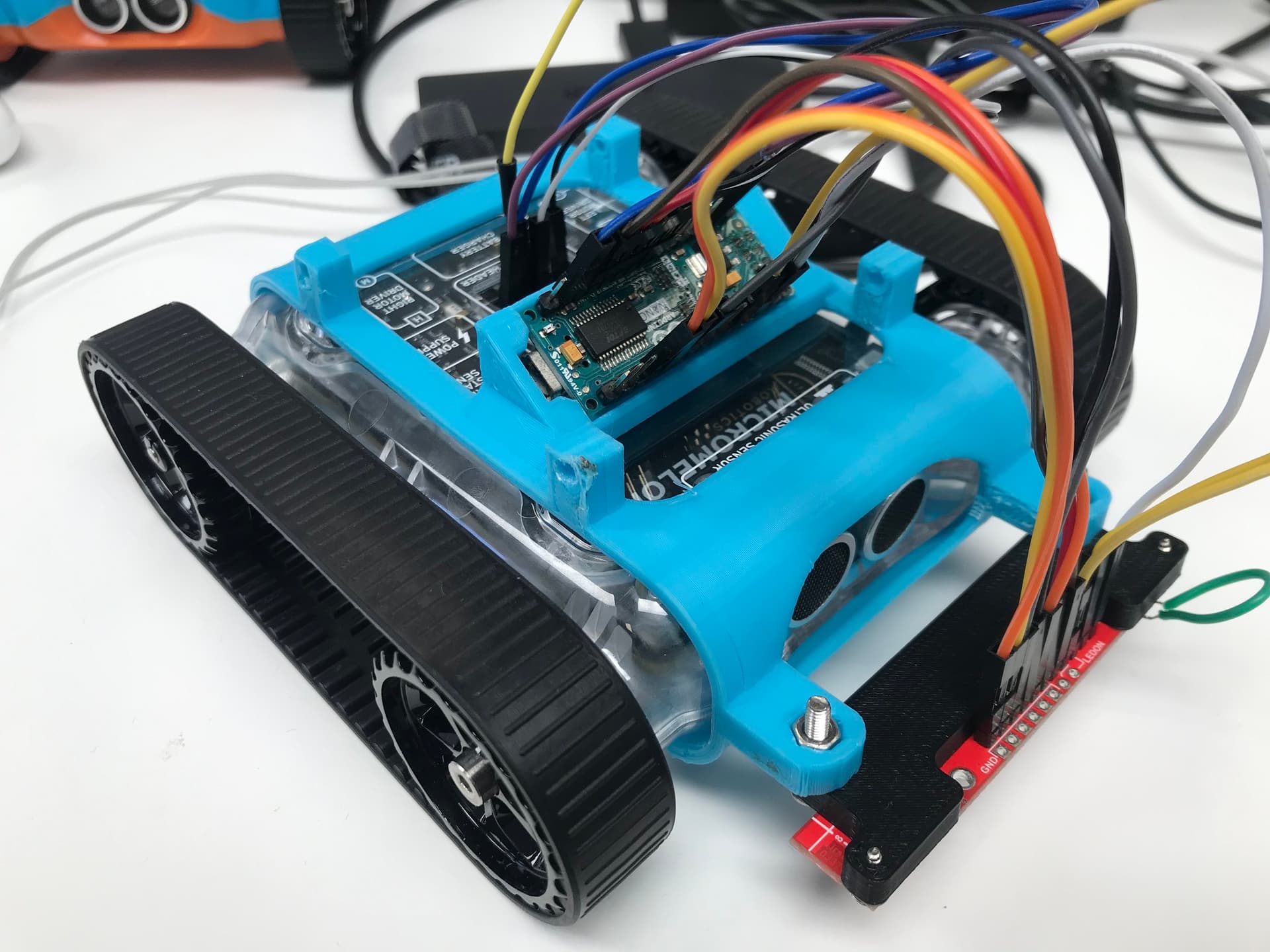
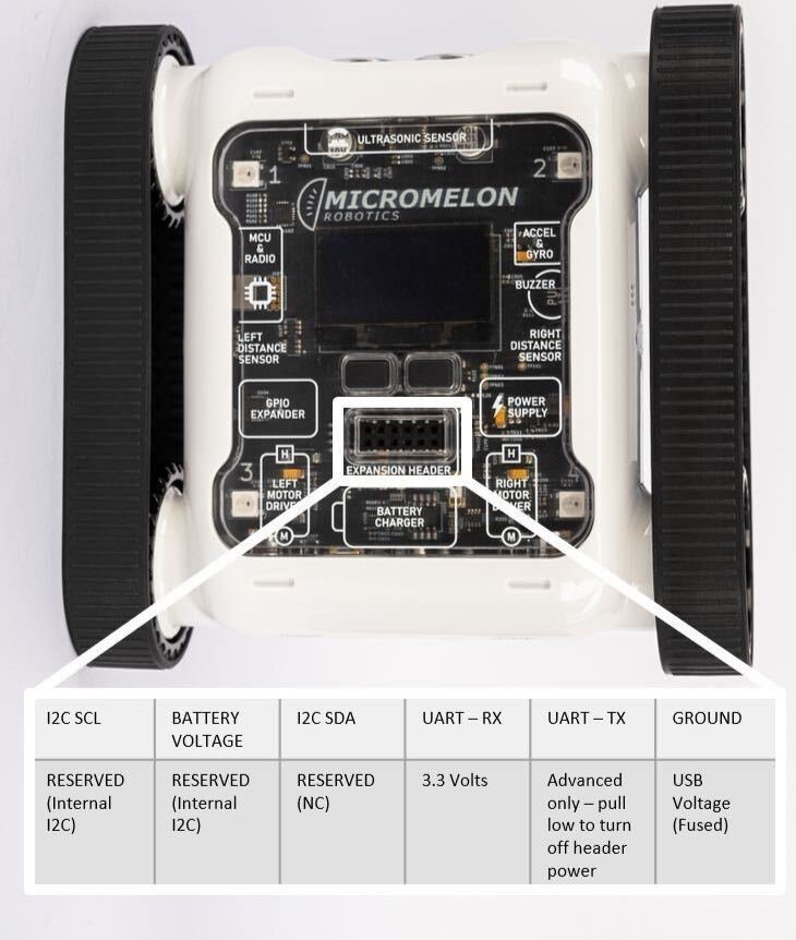
Expansion Header Pinout
12-pin header. Pin 1 is top-left; top row reads left-to-right, bottom row reads right-to-left.
Note: The Rover’s power switch should be in the on position when the other device is powered on. Not doing so may cause the Rover to be back-powered, even if the 3.3V and GND pins aren’t connected.
Rover UART Packets
The Rover follows a particular format for UART data, this format allows commands to be sent to the Rover from an external device. Most languages have a function that handles the start bits, parity bits, and stop bits, so all that needs to be given is the data frame. The structure is:
| Start byte | Operation byte | Register byte | Data length byte | Data byte |
|---|---|---|---|---|
Always 0x05 | 0x00 to read, 0x01 to write | Enum corresponding to a command | Number of bytes of data | Data related to the command |
- The start byte is always
0x05, which tells the Rover’s UART to begin reading the transmission line. - The operation byte is set based on whether the external device is going to read data (
0x00) from the Rover or send commands (0x01) by writing data. - The register byte corresponds to the command being sent.
- The data length byte is the number of bytes in the data.
- The data byte is the data related to the command.
Software Interfacing
The final step is writing a program to initialise the connection, create packets, and send them. Implementation depends on the secondary device being used, but generally this is in either Python or C++.
For a Python implementation, see the OpenMV UART guide. For a C++/Arduino implementation, see the Arduino UART guide.