Using I2C and an Arduino Nano, a QTR-8RC line sensor array can be attached to the Rover for advanced line following. This guide is a showcase of how it can be done.
An overview of the I2C protocol and how to use it with the Rover can be found in the  Related resourceHow to use I2CUse I2C on the Micromelon Rover to communicate with external devices like servo drivers, sensor arrays, or an Arduino..
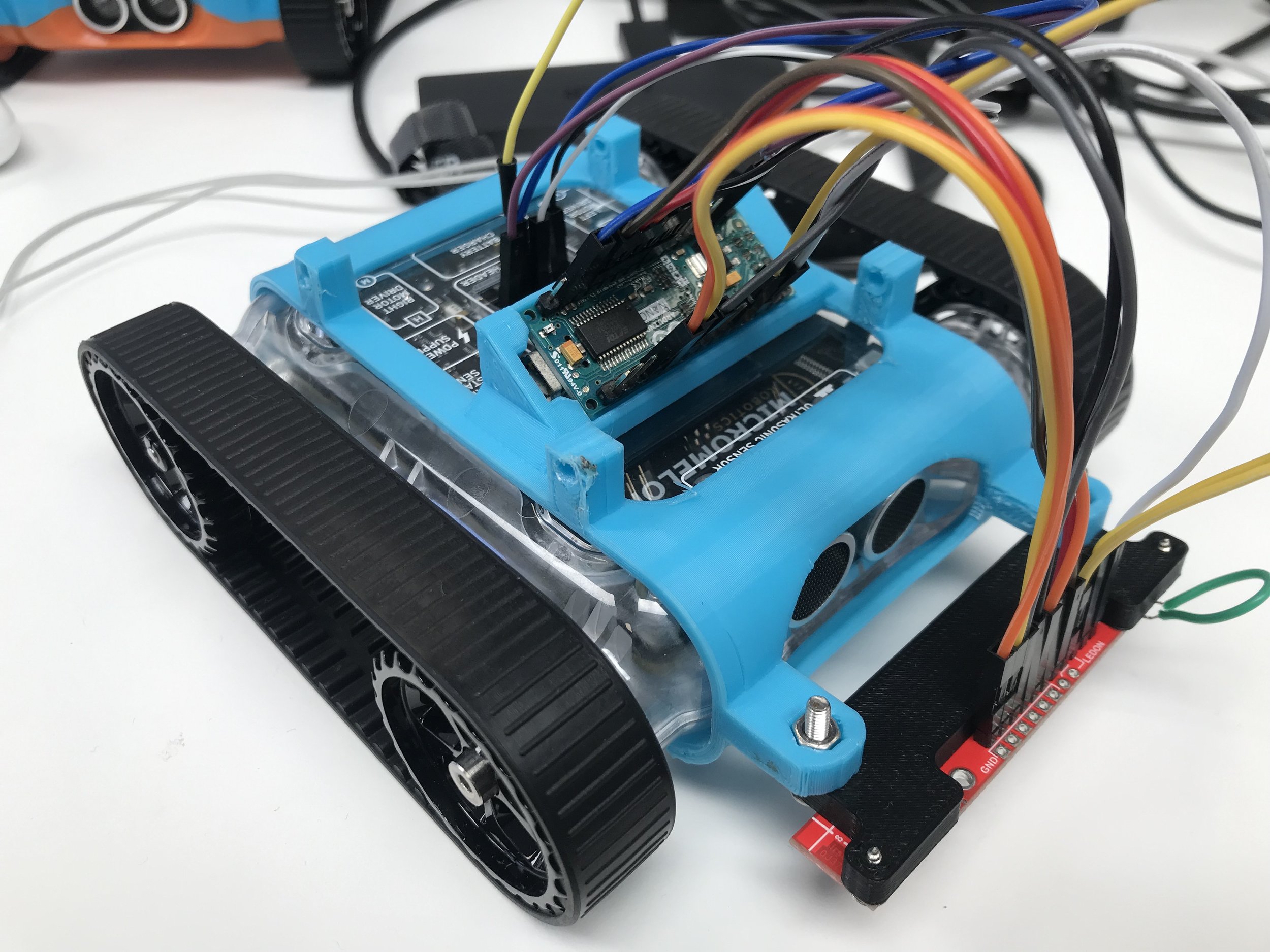
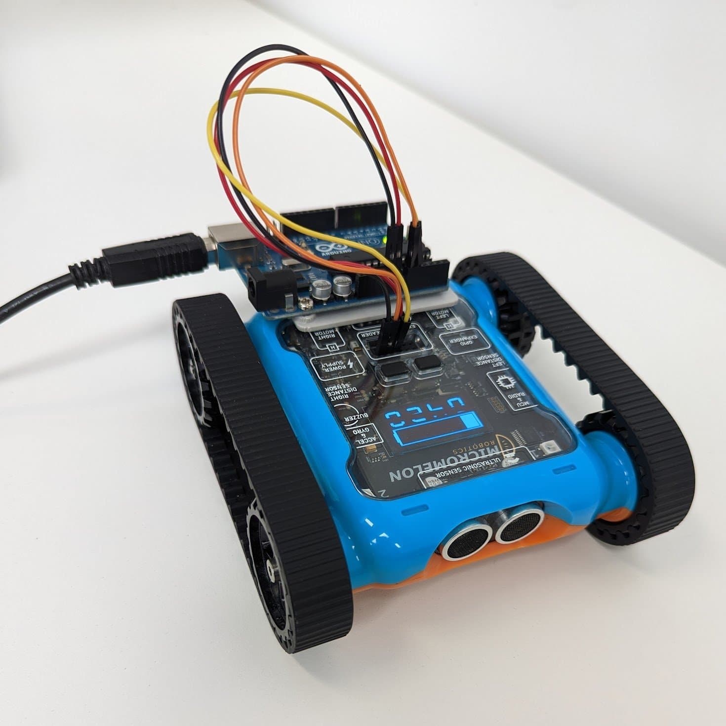
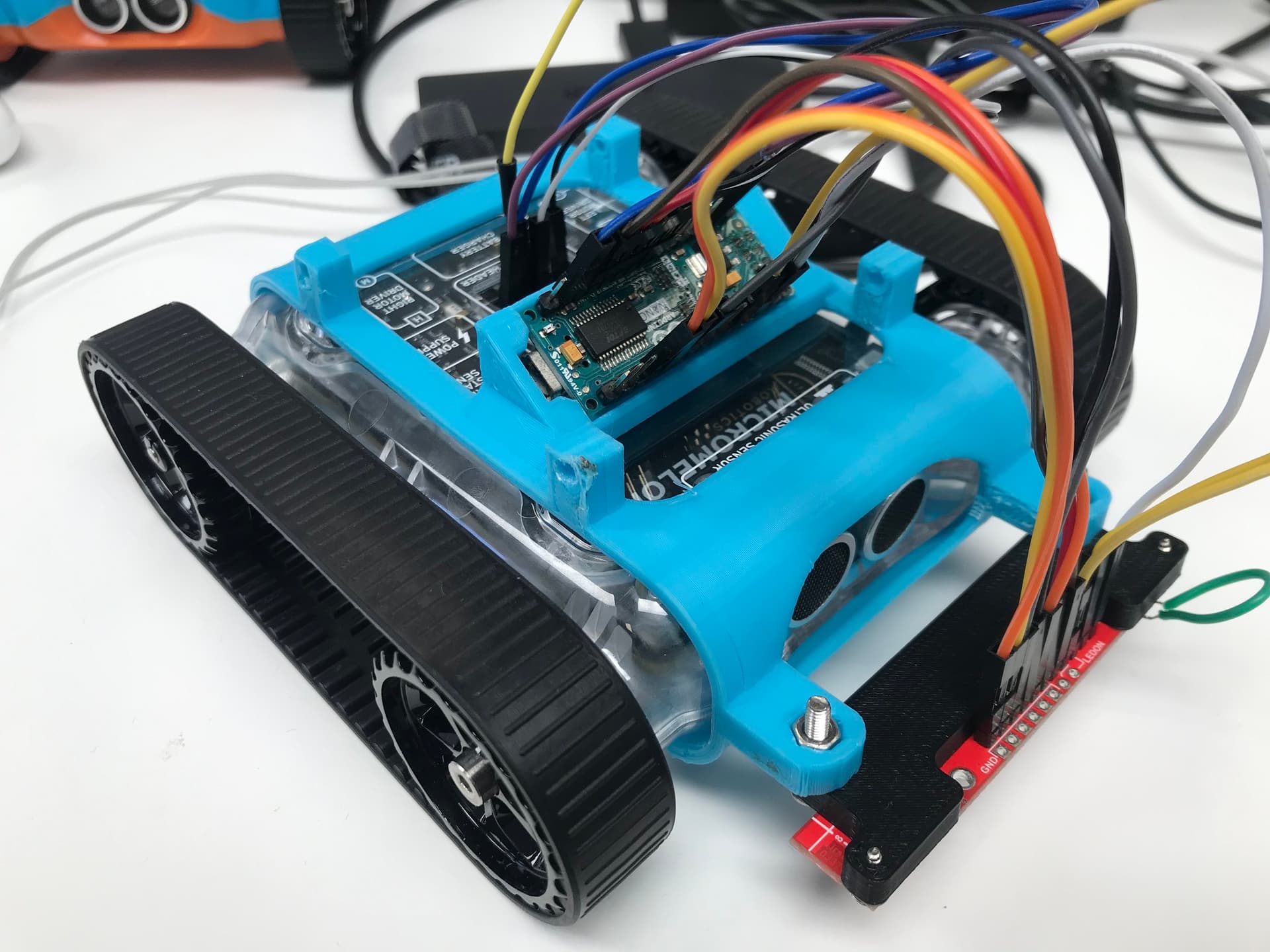
Arduino Nano + QTR-8RC sensor array mounted on the Rover
The Sensor (QTR-8RC)
The Pololu QTR-8RC is an array of 8 infrared sensors spaced approximately 9.5 cm apart. The advantage of using 8 sensors for line following is that the Rover’s speed can be significantly increased, there’s a much lower chance of losing the line when moving. When paired with the QTR library, the sensor array calculates the line’s position relative to it, returned as a value between 0 and 8000. If the line is lost, the sensor also remembers the last sensor that saw the line in the array.
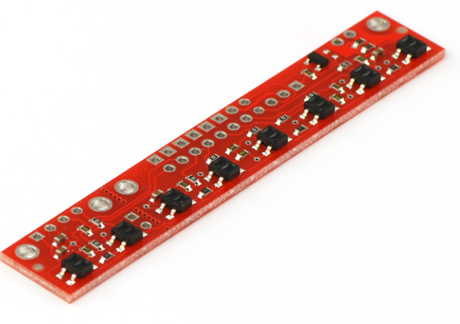
Pololu QTR-8RC infrared line sensor array
The Arduino
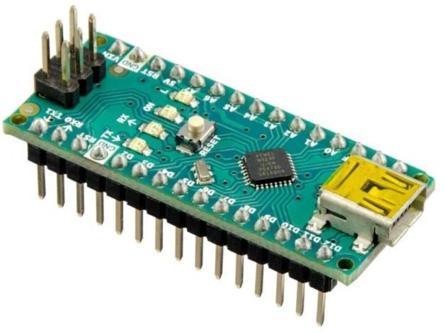
Arduino Nano microcontroller
The Arduino Nano is the microcontroller used to control the QTR sensor. With the sensor plugged in, the Arduino uses the QTR library to locate the line’s position under the sensor. The Arduino then communicates with the Rover over I2C, the Rover requests data and receives a buffer containing the line’s location determined by the infrared sensor array. This buffer is 2 bytes because the maximum value of 8000 is larger than what a single byte can hold.
#include <QTRSensors.h>
#include <Wire.h>

#define ADDRESS 10
QTRSensors qtr;

const uint8_t SensorCount = 8;
uint16_t sensorValues[SensorCount];

uint16_t position = 2000;

void setup() {
  Wire.begin(ADDRESS);
  Wire.onRequest(readSensor);
  // Configure the sensors
  qtr.setTypeRC();
  qtr.setSensorPins((const uint8_t[]){9, 8, 7, 6, 5, 4, 3, 2}, SensorCount);

  delay(500);
  pinMode(LED_BUILTIN, OUTPUT);
  digitalWrite(LED_BUILTIN, HIGH);

  for (uint16_t i = 0; i < 400; i++) {
    qtr.calibrate();
  }
  digitalWrite(LED_BUILTIN, LOW);
}

void loop() {
  position = qtr.readLineBlack(sensorValues);
}

void readSensor() {
  byte buf[2] = {(position & 0xFF00) >> 8, position & 0xFF};
  Wire.write(buf, 2);
}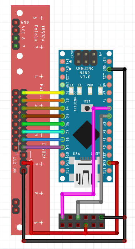
Wiring diagram, Arduino Nano connected to the Rover over I2C
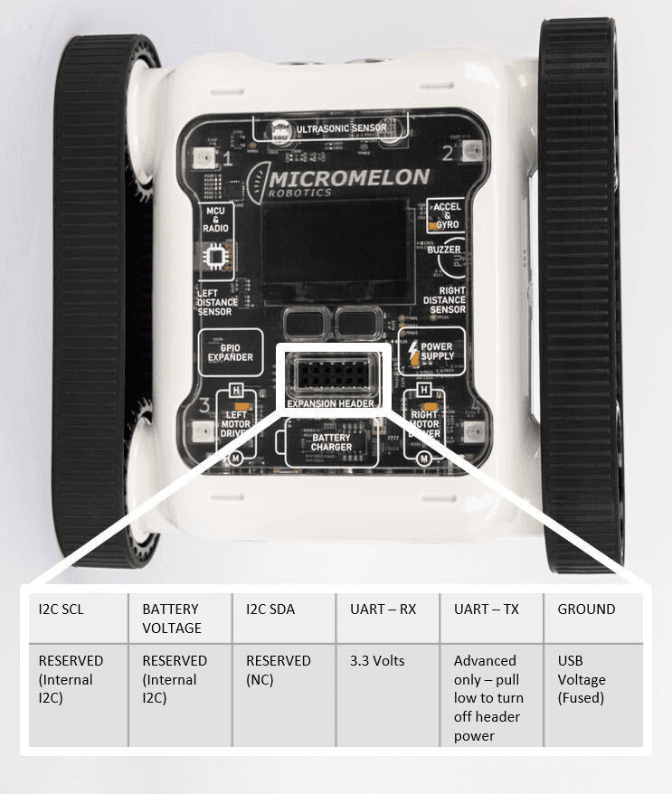
Expansion Header Pinout
12-pin header. Pin 1 is top-left; top row reads left-to-right, bottom row reads right-to-left.
The Rover
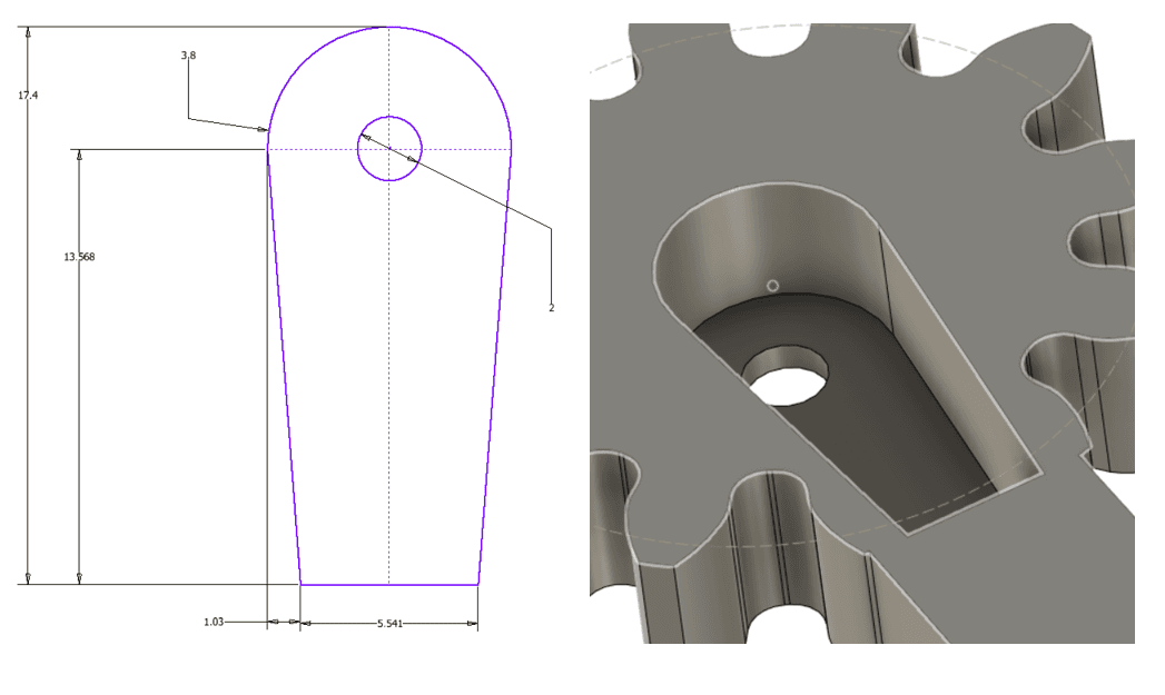
A 3D-printed mount was designed to hold the Arduino and the line sensor array. Once all the electronics were connected, code to request data from the Arduino was uploaded to the Rover. The snippet below uses the read_sensor function to receive incoming data from the Arduino.
ADDRESS = 10
REGISTER = 0x1
def read_sensor():
packet = I2C.read(ADDRESS, REGISTER, 2)
packet = (packet[0] << 8) | packet[1]
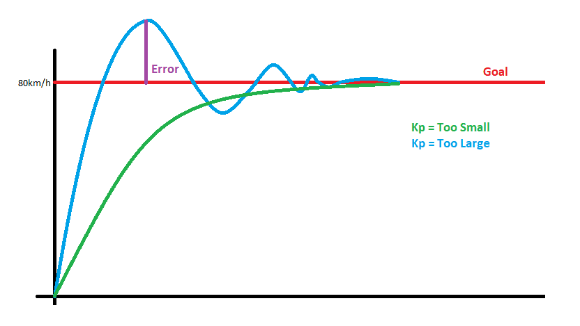
return packetThese concepts were then assembled to create a PID line follower.
Going Further
With PID tuning and a well-mounted sensor array, the Rover can follow tight curves at impressive speeds. Try adjusting the PID constants to see how they affect tracking accuracy and responsiveness, or experiment with different line layouts to push the system to its limits.