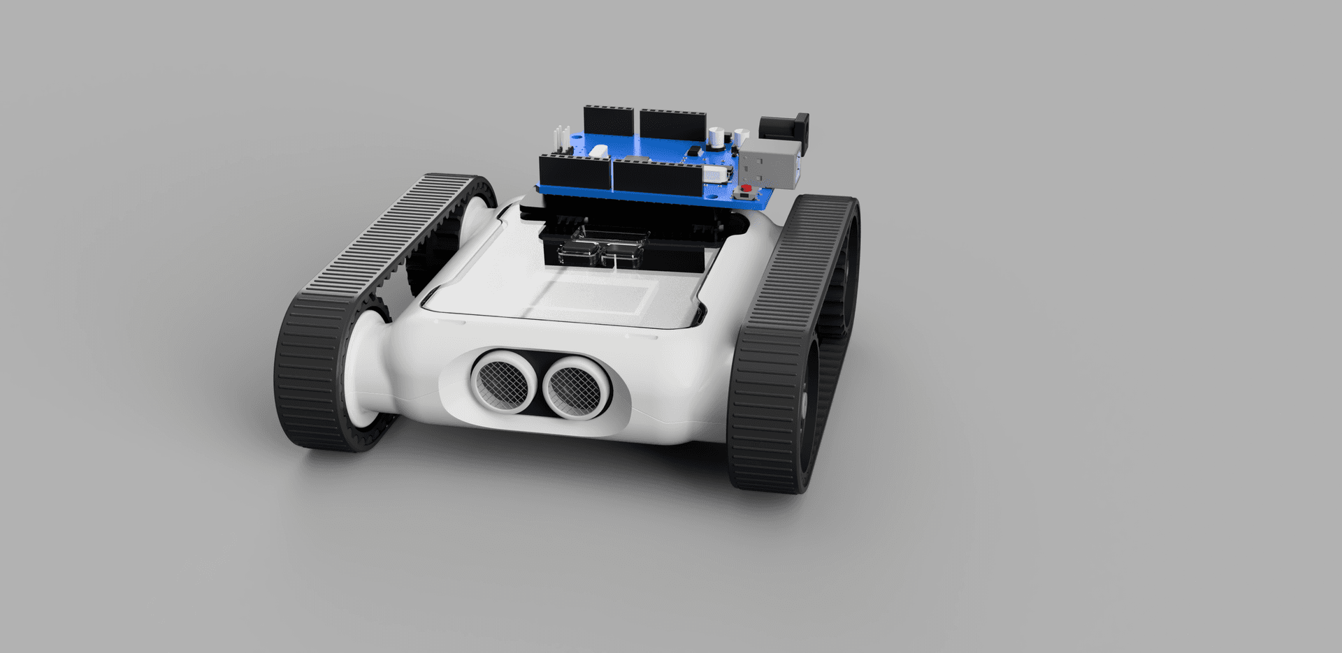
The Micromelon Rover comes with an expansion header that allows for the connection of various additional devices. This guide will outline how to connect an Arduino Uno and use it to control the Rover via UART.
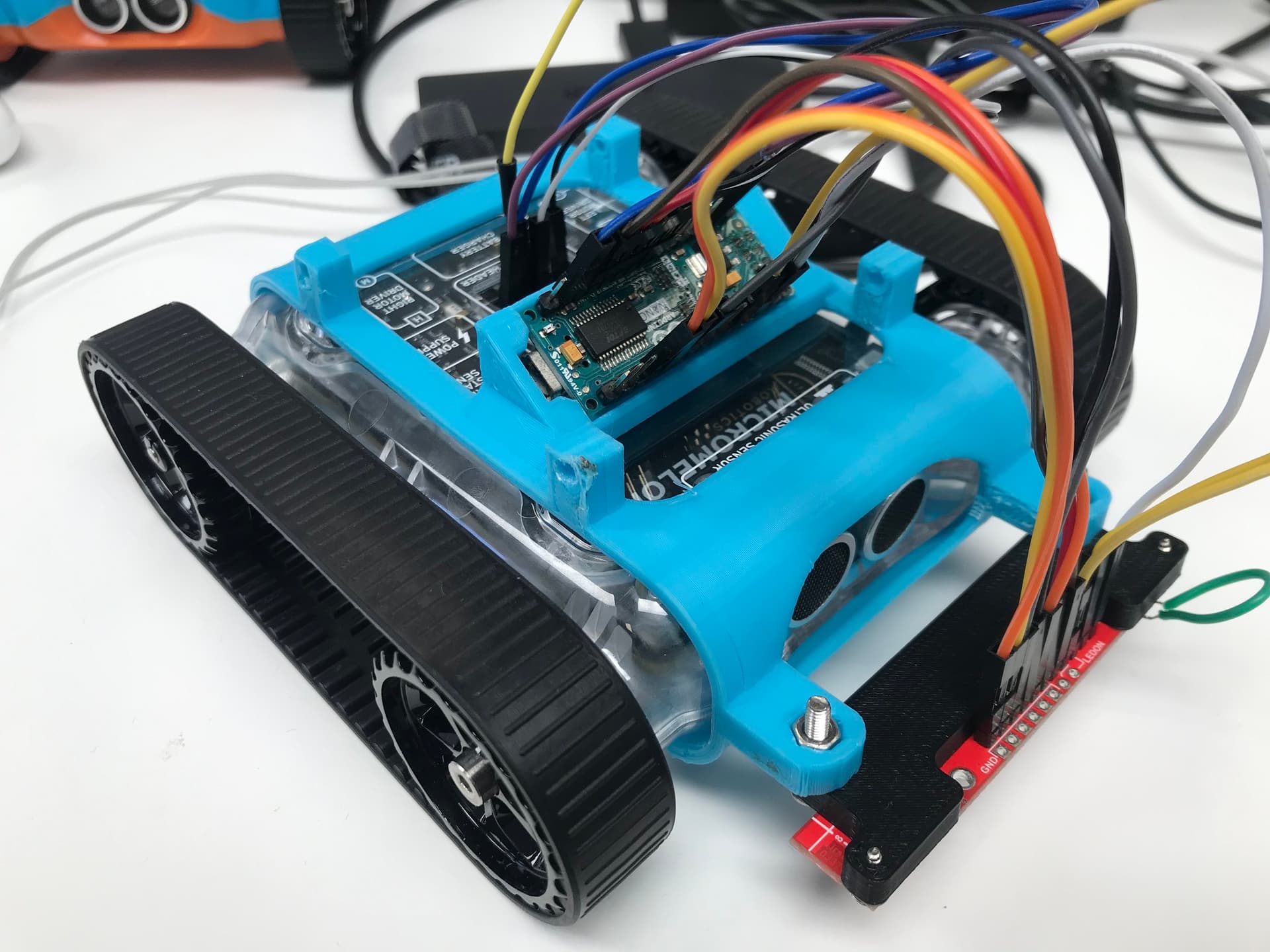
An Arduino Uno wired to the Micromelon Rover expansion header
Hardware Setup
First, the Rover’s RX and TX pins must be connected to the Arduino. Software serial will be used instead of the hardware serial ports (pin 0 and pin 1) on the Arduino since these pins are also used when communicating to the Arduino via the USB port.
In this guide, pins A0 and A1 will be used for this. However, any pair of GPIO pins can be used.
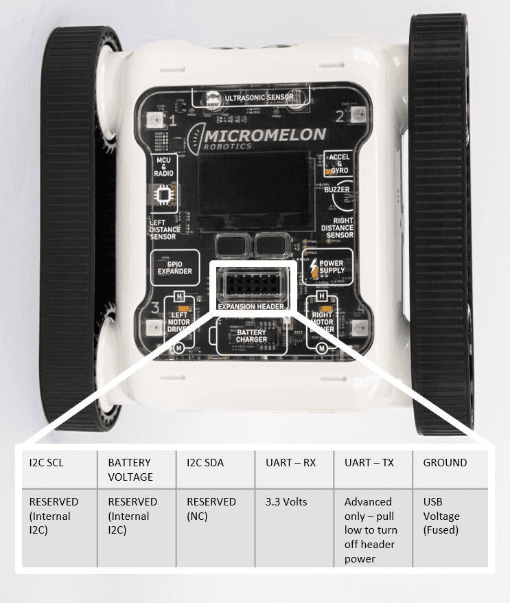
Expansion Header Pinout
12-pin header. Pin 1 is top-left; top row reads left-to-right, bottom row reads right-to-left.
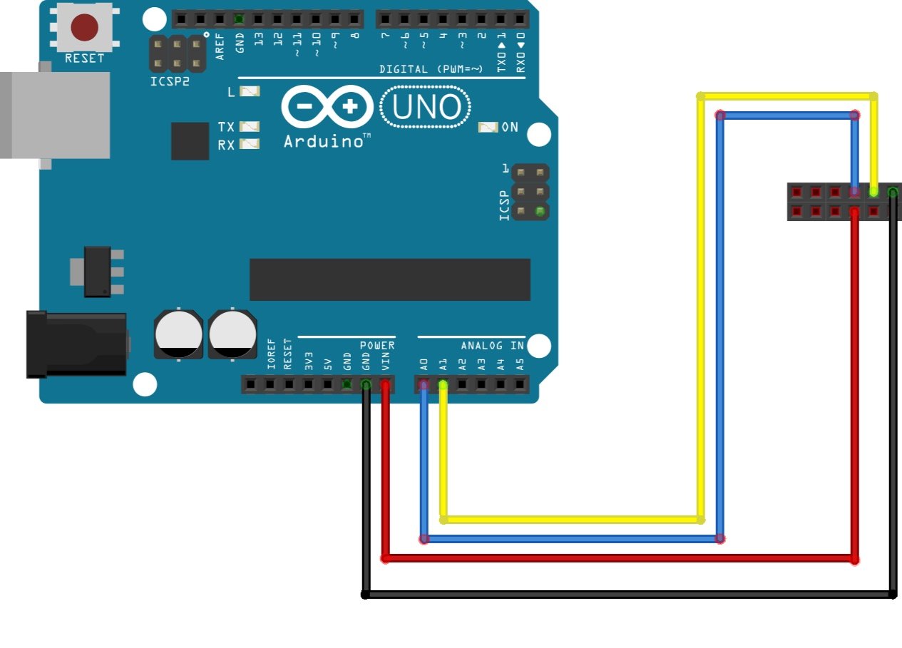
Example wiring: Arduino A0/A1 to Rover TX/RX, plus GND
Rover UART Initialisation
When programming the Arduino, the Arduino IDE is the easiest-to-use development environment. It has a lot of included libraries which will make sending UART packets much more straightforward, and everything can be kept inside a single file. All of the code for this project can be stored in an Arduino sketch (.ino file), which can be created using the Arduino IDE.
When working with Arduino sketches, there must be both a setup and a main function. The specifics of what goes in each will be explained later, but the setup function runs once at the program’s start. After this, the loop function will run until the program ends. Typically the setup function would be written before the loop function.
Before any functions are written, any required libraries must be imported, and global variables must be declared.
Since we will not use the hardware UART pins, a software serial must be set up. As the name suggests, this library is designed to replicate the functionality of hardware serial pins. To set up software serial, we must accomplish the following:
-
Import SoftwareSerial.h
-
Define RX and TX pins, which are A0 and A1, respectively
-
Create the SoftwareSerial object
#include <SoftwareSerial.h>

const byte rxPin = A1;
const byte txPin = A0;

SoftwareSerial roverSerial = SoftwareSerial(rxPin, txPin);
The next step is to set up the Arduino and Rover to send and receive UART packets. To do this, we must accomplish the following:
-
Set the RX and TX pin modes
-
Begin serial
-
Set the Rover to “Expansion Mode”
The command to set the Rover to “Expansion Mode” must be sent first. For this to happen, the data packet must be constructed as follows:
| Start Byte | Operation Byte (Read/Write) | Register Byte | Data Length Byte | Data |
|---|---|---|---|---|
| 0x55 | 0x01 (Writing) | 26 | 1 | 1 (Bluetooth Mode) |
This information must be stored in a buffer and written out to the serial port to send this packet over UART.
void setup() {
pinMode(rxPin, INPUT);
pinMode(txPin, OUTPUT);
roverSerial.begin(115200);
delay(50);
uint8_t armPacket[5] = {0x55, 0x01, 26, 1, 1};
roverSerial.write(armPacket, 5);
delay(50);
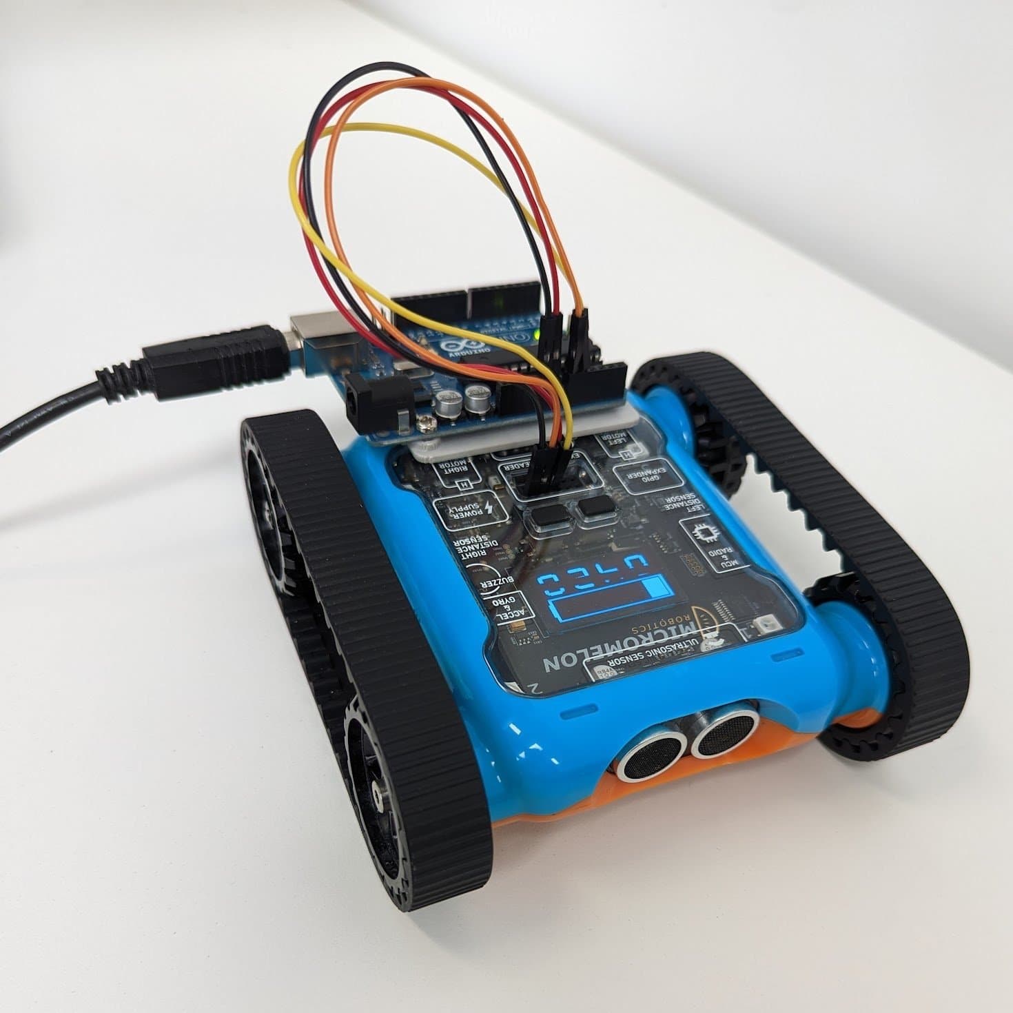
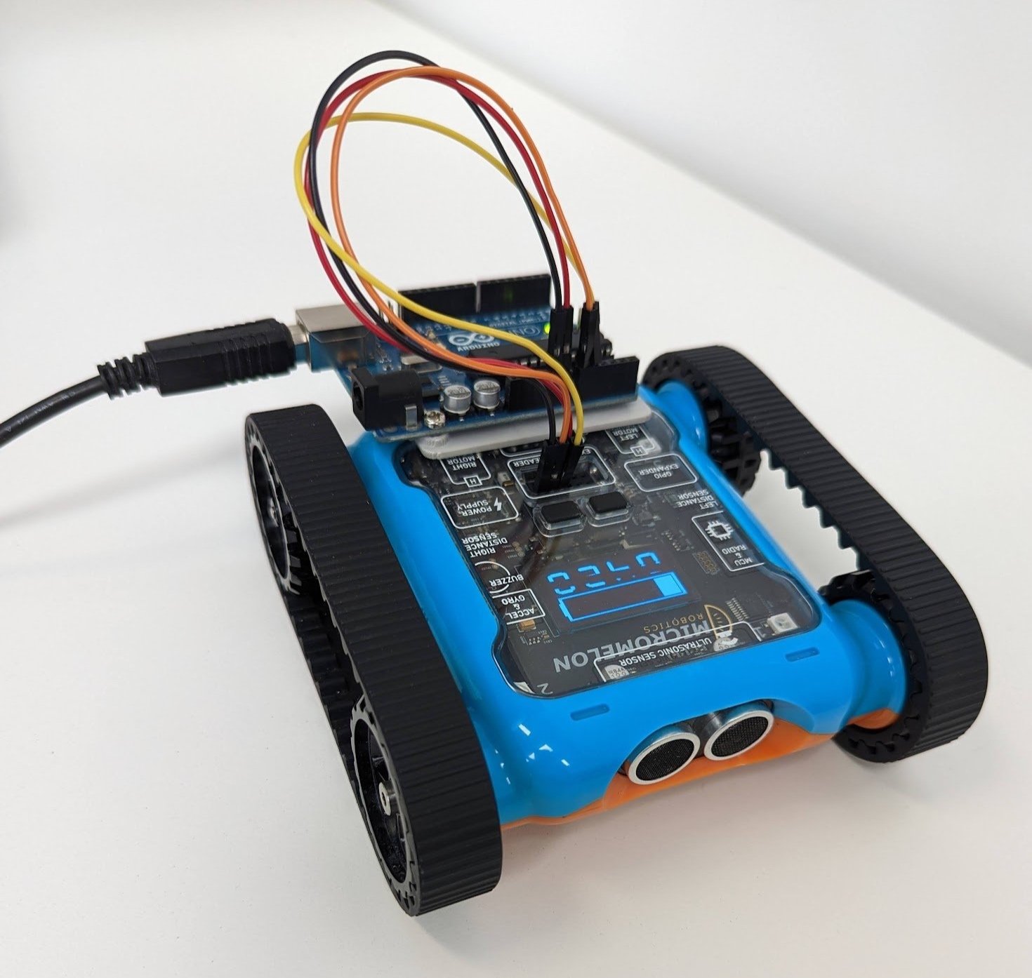
}Uploading this code to the Arduino should cause the Rover to enter the required “Expansion Mode”. To check if this has been done, the Rover’s LCD should read “Expansion Mode”, where the bot ID used to be.
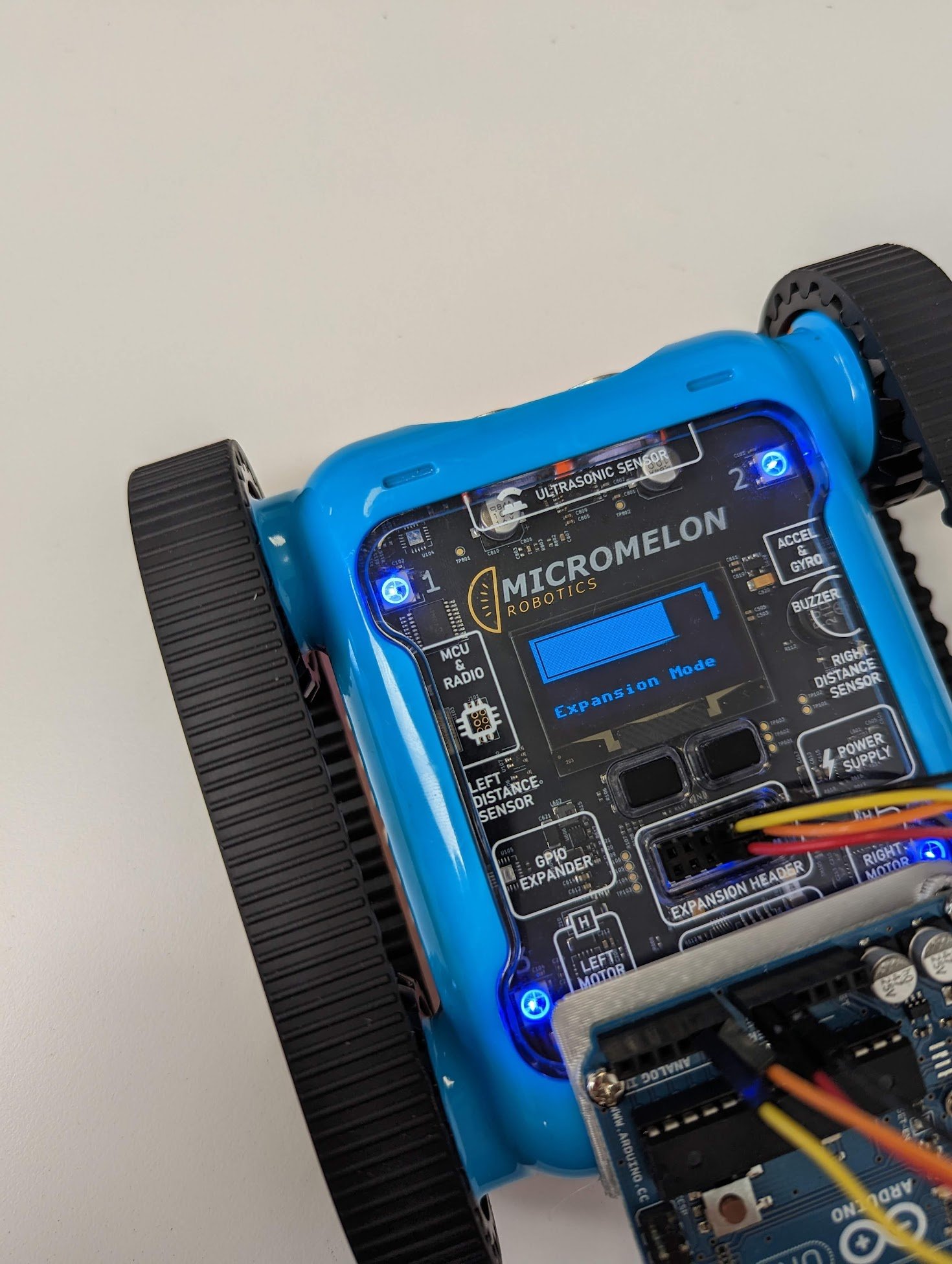
Rover LCD displaying ‘Expansion Mode’ once the Arduino takes control
Sending Rover Commands
Once the Rover is in “Expansion Mode”, other commands can be sent to the Rover.
The move motors command is one of the most useful commands to know how to send to the Rover. Similar to the expansion mode command, the motor movement packet is constructed as follows:
| Start Byte | Operation Byte (Read/Write) | Register Byte | Data Length Byte | Data |
|---|---|---|---|---|
| 0x05 | 0x01 (Writing) | 0 | 2 | Left speed, right speed |
We recommend creating a separate function that handles moving the motors. Anytime this is called, the motors should move based on your inputs to this function.
It should be noted that the motors must be encoded as an integer from -127 to 127. In this example, it will be assumed that the input to the ‘moveMotors’ function will be from -30 to 30 and must be scaled accordingly.
void moveMotors(int8_t leftSpeed, int8_t rightSpeed) {
  int8_t scaledLeftSpeed = leftSpeed * (127/30);
  int8_t scaledRightSpeed = rightSpeed * (127/30);

  uint8_t packet[6] = {0x55, 0x01, 0, 2, scaledLeftSpeed, scaledRightSpeed};
  roverSerial.write(packet, 6);
  delay(50);
}
For this example, the Rover should move forwards until the program is finished. The final step is to implement this function into the main loop.
void loop() {
   moveMotors(30, 30);
}
Putting all of this together should result in the following code:
#include <SoftwareSerial.h>

const byte rxPin = A1;
const byte txPin = A0;

SoftwareSerial roverSerial = SoftwareSerial(rxPin, txPin);

void moveMotors(int8_t leftSpeed, int8_t rightSpeed) {
  int8_t scaledLeftSpeed = leftSpeed * (127/30);
  int8_t scaledRightSpeed = rightSpeed * (127/30);

  uint8_t packet[6] = {0x55, 0x01, 0, 2, scaledLeftSpeed, scaledRightSpeed};
  roverSerial.write(packet, 6);
  delay(50);
}

void setup() {
  pinMode(rxPin, INPUT);
  pinMode(txPin, OUTPUT);

  roverSerial.begin(115200);

  uint8_t arm_packet[5] = {0x55, 0x01, 26, 1, 1};
  roverSerial.write(arm_packet, 5);
  delay(50);
}

void loop() {
  moveMotors(30, 30);
}
Upload this sketch to your Arduino and the Rover should drive forward continuously. From here you can extend the loop() function with sensor readings, conditional logic, or timed sequences to build more complex behaviours.