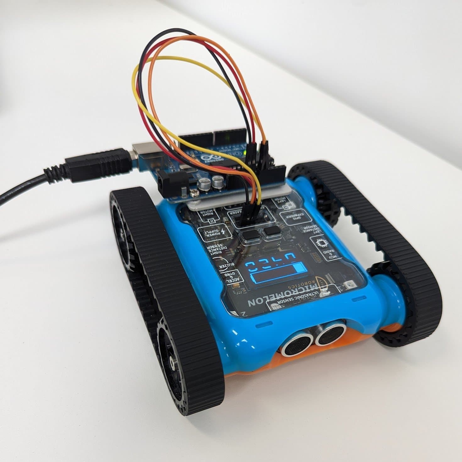
The Micromelon Rover comes with an expansion header that allows the connection of various additional devices. In this guide we’ll connect an OpenMV camera and use it to control the Rover over UART. Our goal is to have the Rover detect objects with the OpenMV and drive towards them.
If you’re not familiar with UART, see the UART guide first.
Hardware Setup
You’ll need to connect the Rover’s RX and TX pins to the OpenMV. You’ll also need to connect the 3.3V and GND pins to power the device.
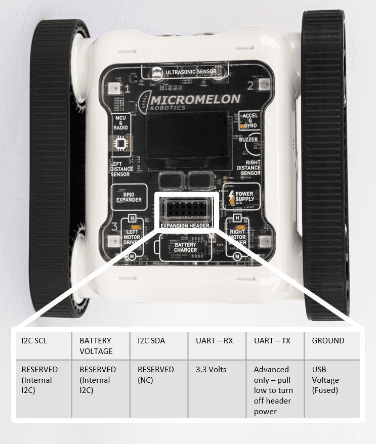
Expansion Header Pinout
12-pin header. Pin 1 is top-left; top row reads left-to-right, bottom row reads right-to-left.

Wiring diagram, OpenMV connected to the Rover’s UART pins
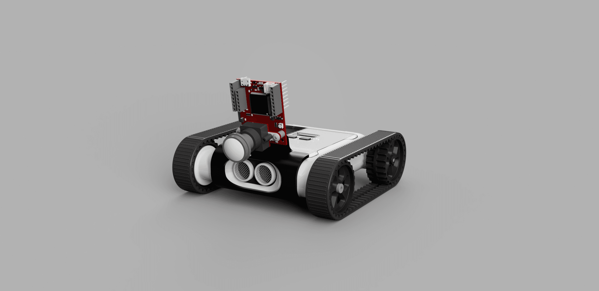
To attach the OpenMV to the Rover, head to Printables or Thingiverse and download the OpenMV clip. To assemble, use 2× M3 (8–10 mm) screws to attach the OpenMV to the clip, then click the clip onto the front of the Rover.
Rover UART Initialisation
When programming the OpenMV, we recommend using the OpenMV IDE, it has built-in camera calibration functionality and makes flashing the OpenMV easy. Since the OpenMV is programmed using MicroPython, you can store all the code for this project in a Python file inside the IDE. The MicroPython documentation provides a good overview of the libraries used.
OpenMV Python files have three key elements. The first step is to import any necessary libraries, constants, and global variables. By default, the sensor, image, and time libraries are imported. You’ll also need to import the pyb library, which gives you access to specific device functionality such as sending UART packets.
import sensor, image, time
from pyb import UART

roverSerial = UART(3, 115200, timeout_char=1000)
The next step is to set up the Rover to receive UART packets by setting it to Expansion Mode. To do this, send a UART data packet in the following format:
| Start byte | Operation byte | Register byte | Data length byte | Data |
|---|---|---|---|---|
0x55 | 0x01 (writing) | 26 | 1 | 1 (Bluetooth Mode) |
To make it easier to send future Rover commands, create packet-building and sending functions so you can call the appropriate command in the main loop.
def build_and_send_packet(operation, command, data=None):
    if data is None:
        data = []

    packet = [0x55, operation, command, len(data)]
    packet.extend(data)
    return packet
This can then be used to arm the Rover:
def arm_rover(state):
    arm_packet = build_and_send_packet(1, 26, [state])
    roverSerial.write(arm_packet)
    time.sleep(0.25)
Uploading this code to the OpenMV should put the Rover into the correct mode. You’ll know it worked if the Rover’s LCD reads Expansion Mode where the bot ID used to be.
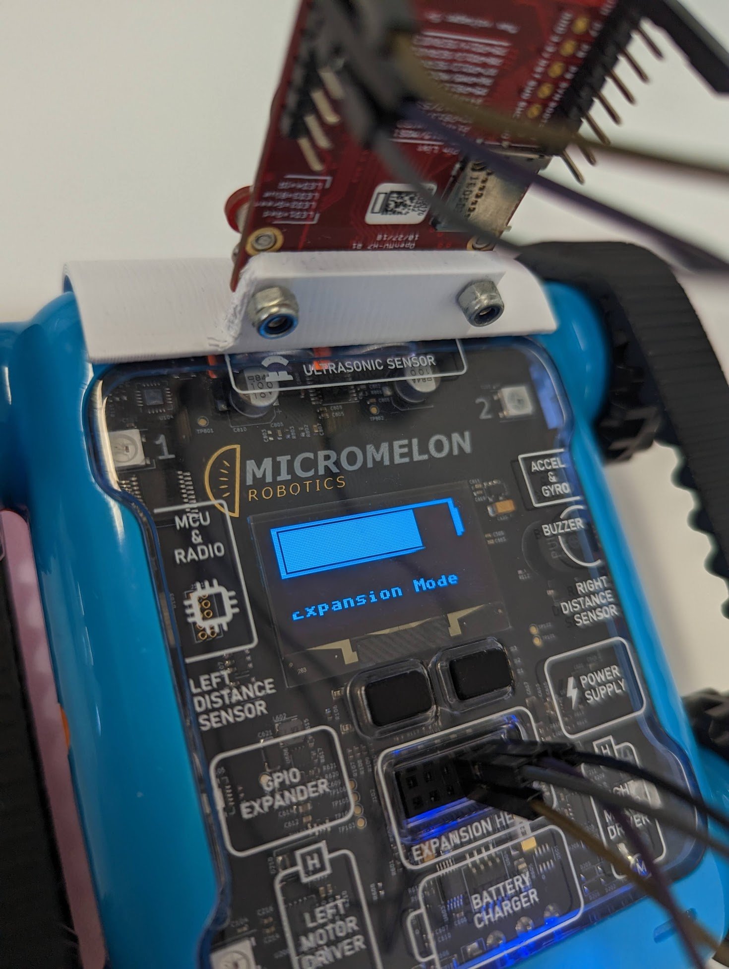
Rover LCD displaying ‘Expansion Mode’
OpenMV Setup
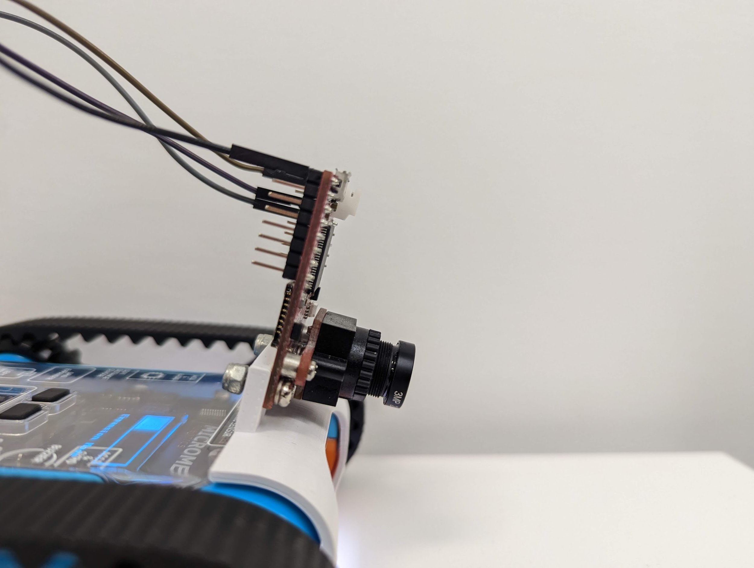
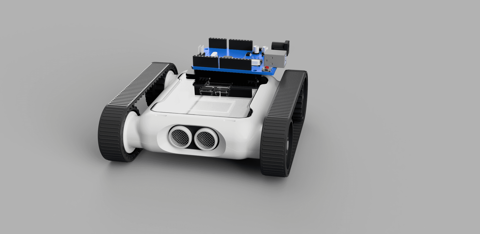
OpenMV mounted on the Rover, angled slightly downward
Now that the Rover is ready to receive commands, set up the OpenMV. When mounting it for object tracking, a slight downward angle is useful, the Micromelon 3D-printed mount handles this.
If the OpenMV is positioned upside down, the image should be flipped accordingly:
sensor.set_vflip(True)
sensor.set_hmirror(True)
You’ll also need to define the clock to ensure each snapshot can be cycled through.
clock = time.clock()  # define the clock

while True:
    clock.tick()
    img = sensor.snapshot()
Running the current code should enable the Rover’s UART expansion header and show the camera’s output inside the OpenMV IDE.
import sensor, image, time
from pyb import UART

roverSerial = UART(3, 115200, timeout_char=1000)

def build_and_send_packet(operation, command, data=None):
    if data is None:
        data = []

    packet = [0x55, operation, command, len(data)]
    packet.extend(data)
    return packet

def arm_rover(state):
    arm_packet = build_and_send_packet(1, 26, [state])
    roverSerial.write(bytearray(arm_packet))
    time.sleep(0.25)

time.sleep(0.5)

arm_rover(True)

sensor.reset()
sensor.set_pixformat(sensor.RGB565)
sensor.set_framesize(sensor.QVGA)
sensor.skip_frames(time=2000)
sensor.set_vflip(True)
sensor.set_hmirror(True)

clock = time.clock()  # define the clock

while True:
    clock.tick()
    img = sensor.snapshot()
    print(clock.fps())
Sending Rover Commands
Once the Rover is in expansion-header mode, you can send commands. One of the most useful is the move motors command. The motor-movement packet is constructed as follows:
| Start byte | Operation byte | Register byte | Data length byte | Data |
|---|---|---|---|---|
0x05 | 0x01 (writing) | 0 | 2 | Left speed, right speed |
We can send a motor movement command using the packet-build-and-send function we made earlier. We’ll assume we want to give a speed from −30 to 30. The speed needs to be scaled and then encoded as a signed binary number before being stored in a packet and sent over UART.
def write_motors(leftSpeed, rightSpeed):
    lSpeed = int(leftSpeed * (127 / 30))
    rSpeed = int(rightSpeed * (127 / 30))

    # 127 = full speed
    # 0 = stop
    # 255 = full backwards

    if lSpeed < 0:
        lSpeed -= 254

    if rSpeed < 0:
        rSpeed -= 254

    packet = build_and_send_packet(1, 0, [lSpeed, rSpeed])
    roverSerial.write(bytearray(packet))
    time.sleep(0.1)
Object Tracking
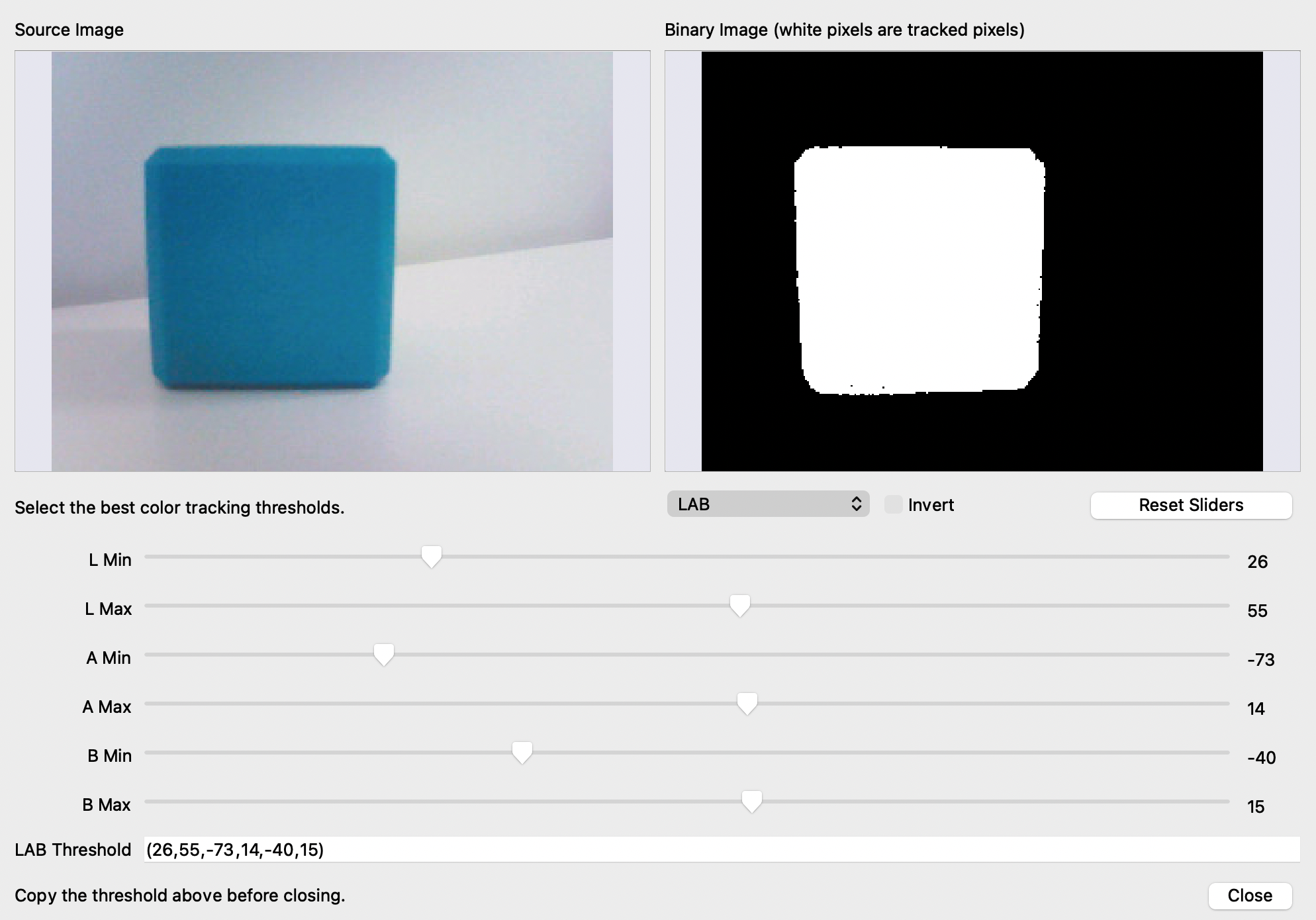
Once we’ve set the colour threshold, we can track objects of that colour using OpenMV’s built-in blob detection. This is a multi-step process executed in the main loop.
Adjust the thresholds in the OpenMV IDE until the tracked colour is clearly defined in the binary image. Copy and store the LAB threshold values in a variable for use when the Rover is armed:
threshold = (26, 55, -73, 14, -40, 15)Using this threshold, we can track objects of this colour:
- Take a camera snapshot.
- Apply thresholding to identify all blobs that match the defined colour.
- The largest blob is likely the object being tracked, save its position.
- Use the coordinates to adjust the Rover based on the object’s position in the snapshot.
To initialise the camera:
OpenMV camera initialisation in the IDE
sensor.reset()                          # Reset and initialise the sensor
sensor.set_pixformat(sensor.RGB565)     # Set the pixel format
sensor.set_framesize(sensor.QVGA)       # QVGA = 320×240
sensor.set_windowing((framew, frameh))  # Window size 240×240
sensor.skip_frames(time=2000)           # Let the camera adjust
sensor.set_vflip(True)
Combine this with the object-detection loop:
while True:
    clock.tick()
    img = sensor.snapshot()

    blobs = img.find_blobs([threshold], area_threshold=1, merge=True)
    blob_area = 0

    for blob in blobs:
        if blob.area() > blob_area:
            blob_area = blob.area()
            img.draw_rectangle(blob.rect(), color=(0, 255, 0))
            img.draw_cross(blob.cx(), blob.cy(), color=(0, 255, 0))
            blob_rel_X_pos = framew / 2 - blob.cx()
            blob_rel_Y_pos = frameh / 2 - blob.cy()
Overall Code
A cohesive snippet combining initialisation and object detection in the main loop:
import sensor, image, time, pyb, math
from pyb import UART, LED

# LED settings (1: red, 2: green, 3: blue, 4: IR)
red_led = pyb.LED(1)
green_led = pyb.LED(2)
blue_led = pyb.LED(3)
ir_leds = pyb.LED(4)
output_pin = pyb.Pin("P0", pyb.Pin.OUT_PP)

red_led.off()

uart = UART(3, 115200, timeout_char=1000)

framew = 240
frameh = 240
motor_speed = 10

sensor.reset()
sensor.set_pixformat(sensor.RGB565)
sensor.set_framesize(sensor.QVGA)
sensor.set_windowing((framew, frameh))
sensor.skip_frames(time=2000)
sensor.set_vflip(True)

# LAB min/max for the blobs, tracking an orange cube in this scenario
threshold = (9, 40, -11, 26, -23, 43)

# Packet is in the format:
# - Start byte (always 0x55)
# - Operation (0x00 = Read, 0x01 = Write)
# - Register (0 is the register of the Motors)
# - Data length (how many bytes of data)
# - Data (respective to the data length)

def build_and_send_packet(opCode, opType, data=None):
    if data is None:
        data = []
    packet = [0x55, opCode, opType, len(data)]
    packet.extend(data)
    return packet

# Takes motor speeds between -30 and 30 and writes them to the Rover
def write_motors(leftSpeed, rightSpeed):
    lSpeed = int(leftSpeed * (127 / 30))
    rSpeed = int(rightSpeed * (127 / 30))

    if lSpeed < 0:
        lSpeed -= 254
    if rSpeed < 0:
        rSpeed -= 254

    packet = build_and_send_packet(1, 0, [lSpeed, rSpeed])
    uart.write(bytearray(packet))
    time.sleep(0.1)

def arm_robot(state):
    packet = build_and_send_packet(1, 26, [state])
    uart.write(bytearray(packet))
    time.sleep(0.25)

clock = time.clock()
print("Arming")
time.sleep(2)  # Wait for the Rover to start up

arm_robot(True)  # Arming packet

while True:
    clock.tick()
    img = sensor.snapshot()

    blobs = img.find_blobs([threshold], area_threshold=1, merge=True)
    blob_area = 0

    for blob in blobs:
        if blob.area() > blob_area:
            # Find the largest blob, overwrite previous coordinates if larger
            blob_area = blob.area()
            img.draw_rectangle(blob.rect(), color=(0, 255, 0))
            img.draw_cross(blob.cx(), blob.cy(), color=(0, 255, 0))
            blob_rel_X_pos = framew / 2 - blob.cx()
            blob_rel_Y_pos = frameh / 2 - blob.cy()
Once the object’s position is being tracked successfully, the next step is to convert the object coordinates into motor-movement commands. There are multiple algorithms to explore for this, experimenting with different approaches will help determine the most suitable one for your requirements.