I2C (I-squared-C) is a communication technique used between multiple integrated circuits. The Micromelon Rover can use the I2C protocol to communicate with other I2C-compatible devices, useful for expanding the Rover’s capabilities with external sensors or additional servos.
How I2C Works
Before using I2C on the Rover, it’s helpful to understand how it works at a basic level.
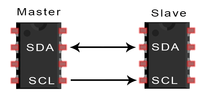
Master and slave devices on an I2C bus (Credit: Scott Campbell, Basics of the I2C Communication Protocol)
I2C communication happens between a master and a slave IC. The clock line (SCL) synchronises the timing of the data sent over the data line (SDA). Data can be sent back and forth between master and slave but not simultaneously, this is called half-duplex. Multiple slaves and masters can be used on a bus, but all require a unique address.
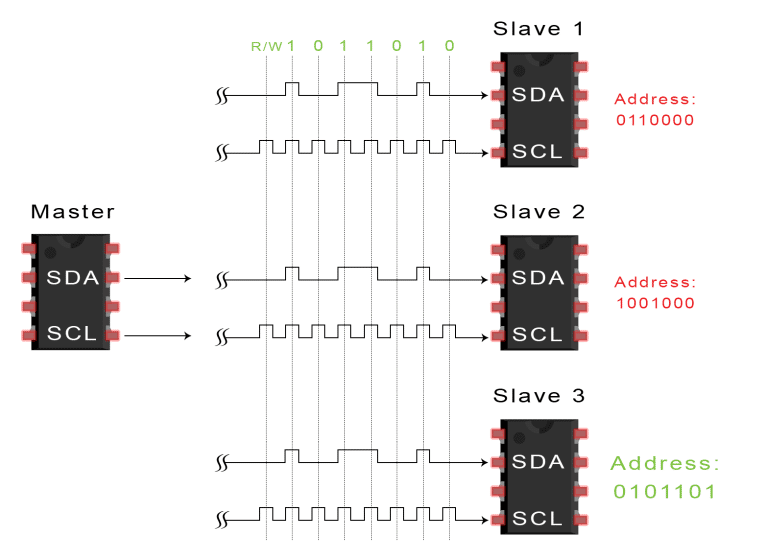
7-bit slave addressing on I2C (Credit: Scott Campbell, Basics of the I2C Communication Protocol)
When a master wants to send a packet to a slave, it starts by sending a 7-bit address over SDA. This establishes which slave is being communicated with. A master can either write data to a slave or read data from a slave; the processes are slightly different.
I2C devices have an address (an identifier) and registers: different locations inside the device that can be read from or written to.
Writing to an I2C Slave
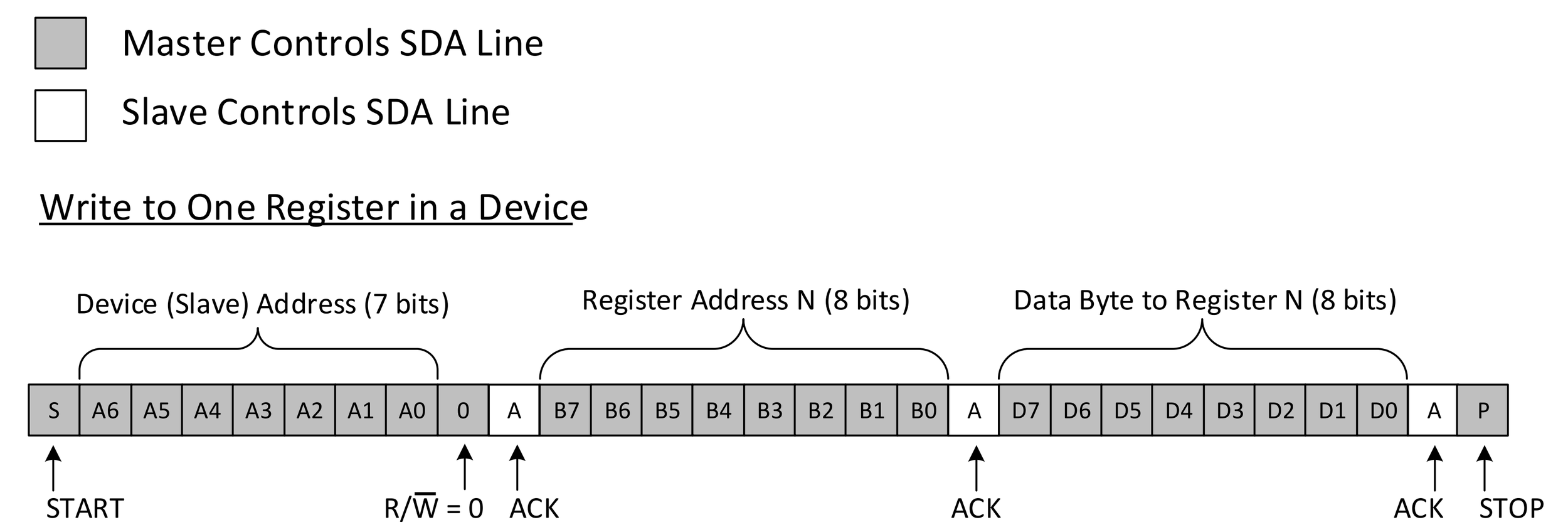
I2C write transaction (Credit: Texas Instruments, Understanding the I2C Bus)
When writing to an I2C device, the master first sends the start signal, followed by the 7-bit address of the slave. Next comes the read/write bit (0 to write, 1 to read). The master waits until the slave sends an acknowledge (ACK) bit on the SDA line. Then the master sends the register address it wishes to write to, the slave acknowledges. The master then transmits the data, with the slave sending an ACK on each byte. The stop condition ends the transmission.
Start and end condition: to signal a start, SDA goes from high to low while SCL stays high. SDA goes from low to high while SCL stays high to signal a stop.
Read/write bit: specifies whether the master wants to read or write. Read = 1, write = 0.
ACK/NACK bit: signals the device has (or hasn’t) received a byte of data. ACK = 0, NACK = 1.
Reading from an I2C Slave
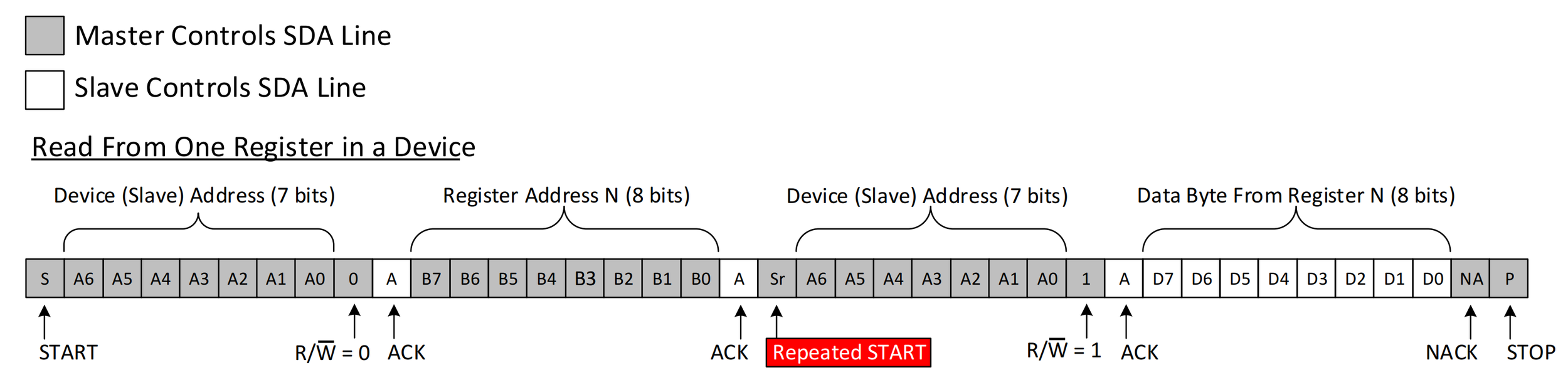
I2C read transaction (Credit: Texas Instruments, Understanding the I2C Bus)
Reading is similar to writing. The master first sends the start signal, followed by the 7-bit slave address. Next comes the read/write bit, and the master waits for the ACK on SDA. The master then sends the register address it wishes to read from and waits for the slave to acknowledge.
The master then sends the start condition again, followed by the slave’s address and a read bit. Once the slave acknowledges, it starts sending a byte of data. The master acknowledges each byte and finally sends a negative acknowledgment (NACK) to signal the slave to stop sending. The stop condition ends the transmission.
I2C on the Rover
Fortunately, the protocols are taken care of when using I2C on the Rover. To wire an I2C device correctly to the Rover, use the pinout below and connect SDA and SCL to the respective pins on the device you’re connecting to.
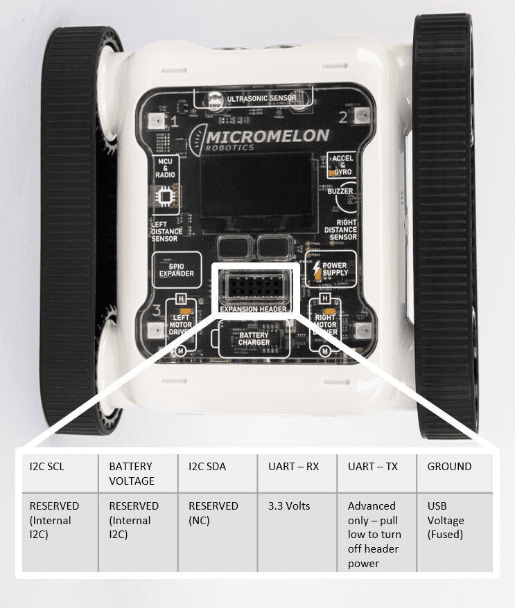
Expansion Header Pinout
12-pin header. Pin 1 is top-left; top row reads left-to-right, bottom row reads right-to-left.
Once connected, the coding is straightforward, there are blocks for reading, writing, and scanning.
I2C Scan
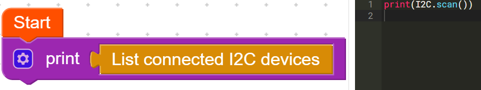
I2C scan block, returns a list of connected I2C addresses
This code returns a list containing the addresses of all I2C devices currently connected to the Rover.
I2C Read
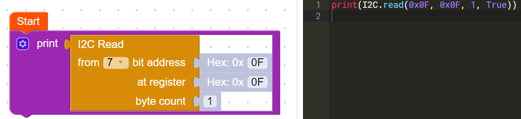
I2C read block, slave address, register, byte count
This block reads from a slave device. You must specify the slave address, the register to read from, and the number of bytes to read. The block returns a list containing each byte of data read from the slave. The data can be greater than 1 byte.
I2C Write
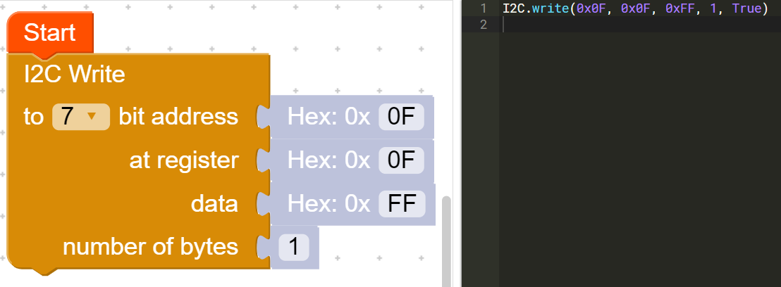
I2C write block, slave address, register, data, byte count
This block writes to a slave device. You must specify the slave address, the register to write to, the data to write, and the data length in bytes. Data can be greater than 1 byte.
Example Uses
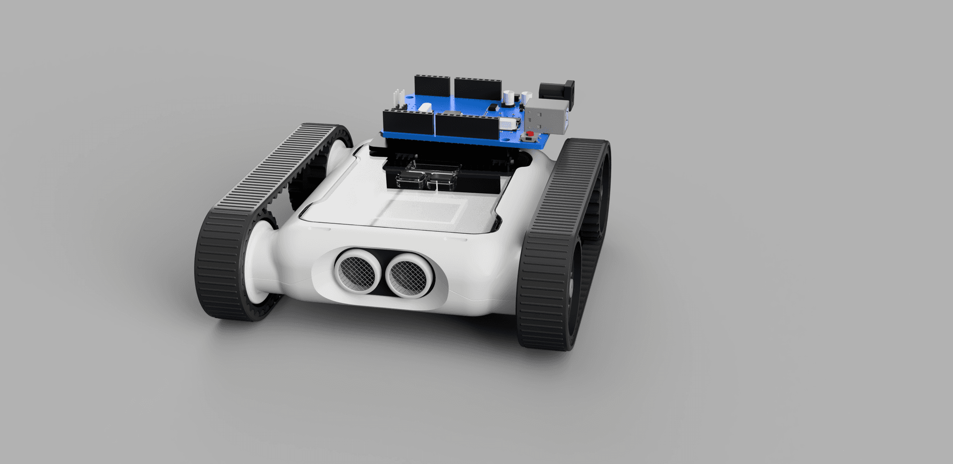
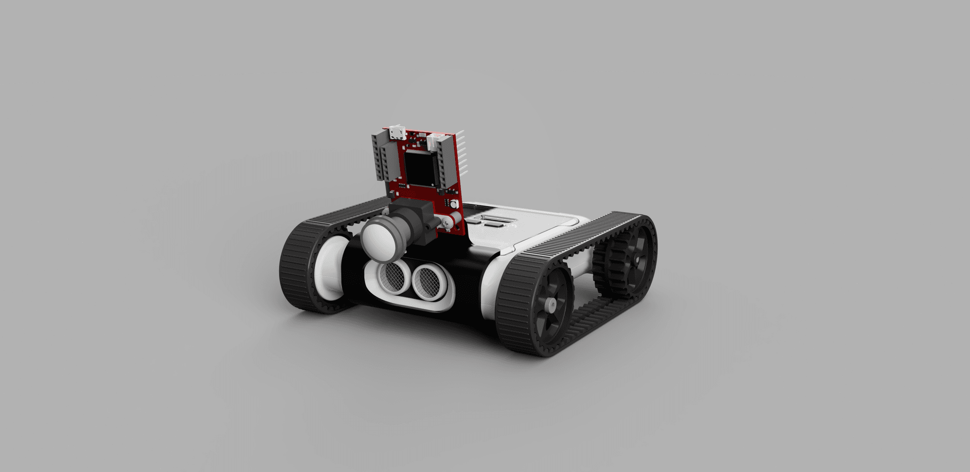
Rover with PCA9685 Servo Driver
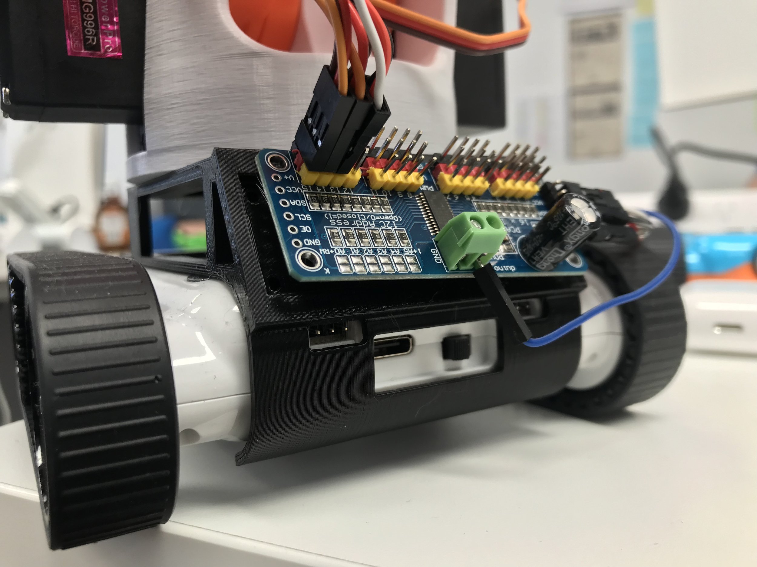
Rover with a PCA9685 16-channel servo driver
The PCA9685 servo driver allows 16 servos to be controlled over I2C. With this device attached, the Rover can control up to 18 servos.
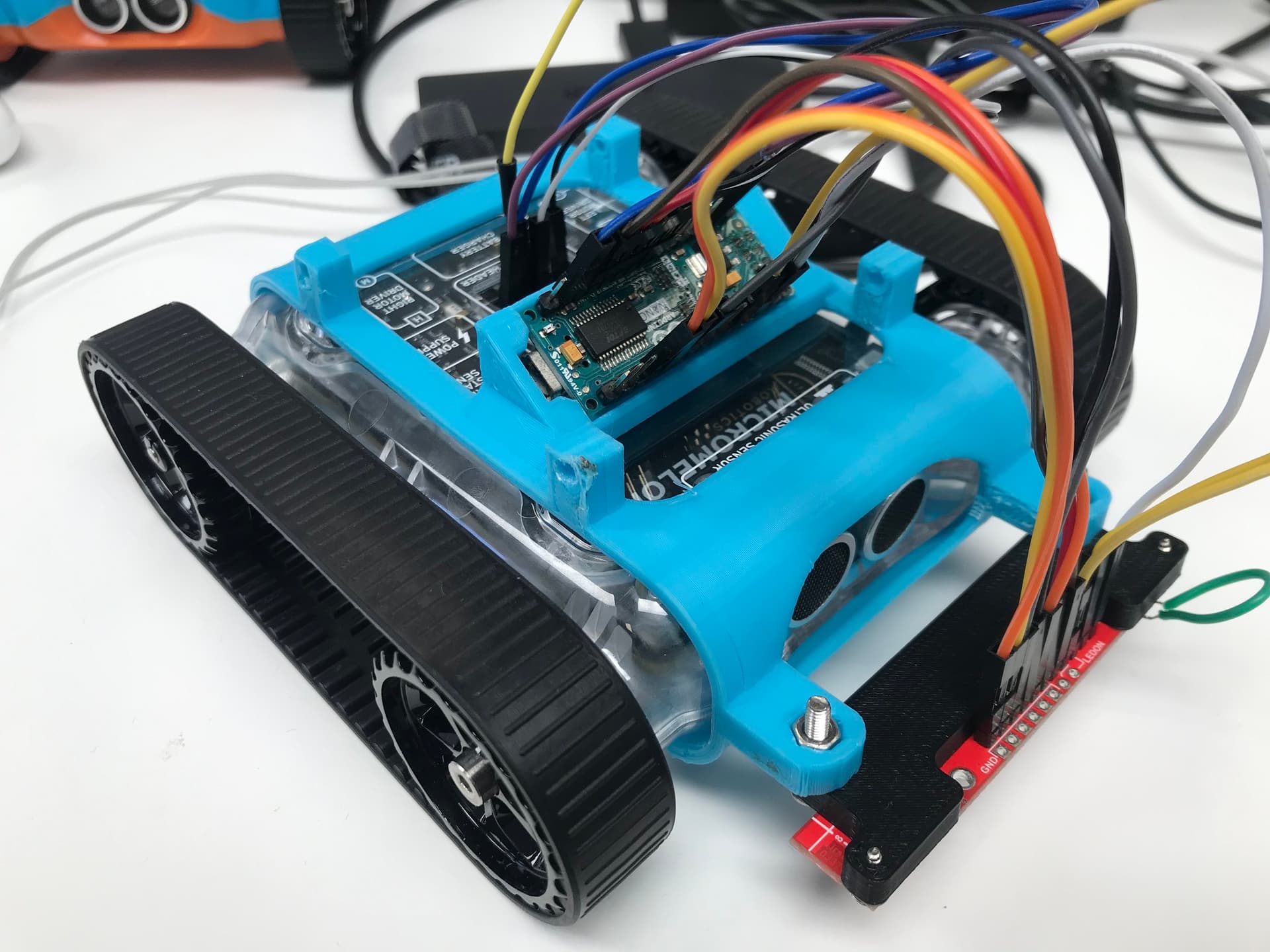
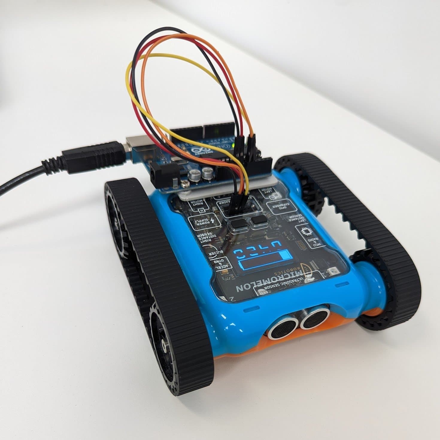
Rover with Arduino Nano
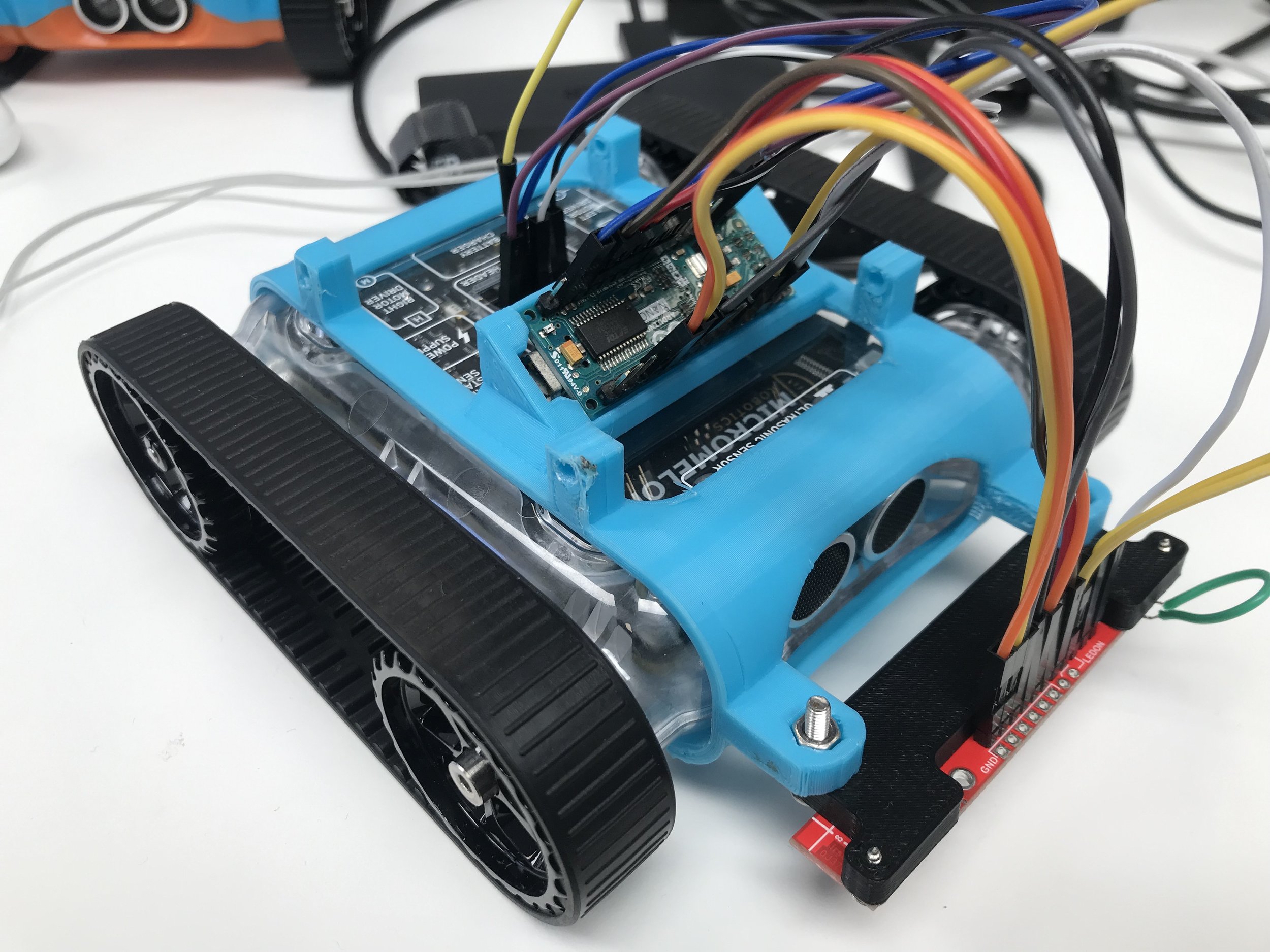
Rover with an Arduino Nano connected over I2C
The Arduino Nano is a highly adaptable microcontroller with many I/O ports. The default I2C ports on the Nano are A4 (SDA) and A5 (SCL). The Rover can use I2C to easily communicate with an Arduino, giving it access to all the I/O ports on the Nano as external sensor ports. In the example above, the Rover uses an Arduino Nano to receive data from a line-sensor array.