Gears can be found in many of the machines around you in everyday life. This guide shows when and where to use gears in your designs.
Advantages and Examples of Gears
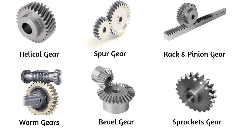
Different types of gears
Many different types of gears exist, each used for a different purpose:
- Increasing the speed or torque of rotations
- Changing the direction of rotation
- Changing the axis of rotation
- Converting rotational movement into linear movement
One of the simplest uses of gears is to change mechanical advantage: a value that represents the amplification of force. A mechanical advantage of 4 means quadrupling the input force.
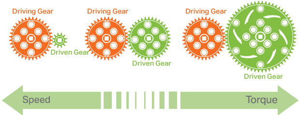
Driver and driven gears (Credit: Salish 274)
When the driver gear has more teeth than the driven gear, speed increases and torque decreases. When the driver gear has fewer teeth than the driven gear, torque increases and speed decreases. The calculation is simple:
Mechanical Advantage = (teeth on driven gear) ÷ (teeth on driver gear)
Designing Gears in Fusion 360
While designing gears traditionally is possible, this guide uses the Spur Gear Add-in from Fusion 360. On a new Fusion part, navigate to Utilities → Add-ins → Add-ins → Spur Gear (there will be two; either will work).
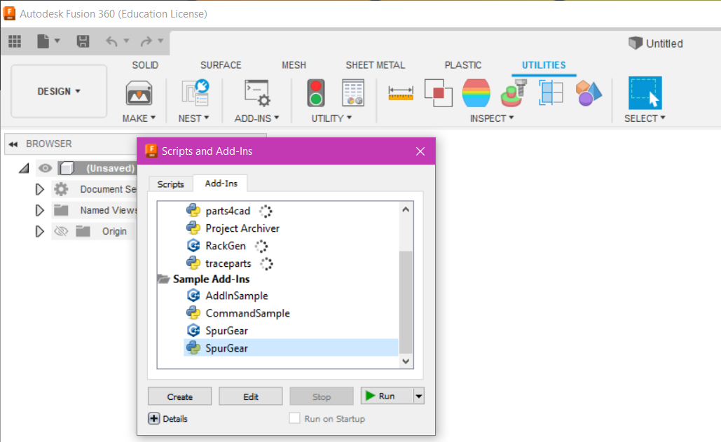
Loading the Spur Gear add-in in Fusion 360
Back in the Solid section, under the Create tab, you’ll now find the new Spur Gear tool. (You’ll need to repeat this for each new part.) Click the Spur Gear option to open the menu.
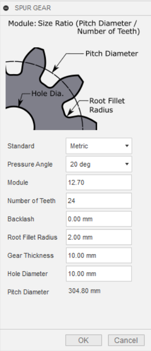
Spur Gear menu
To make your gear, go through the following options:
- Pressure angle: the angle at which the teeth of two gears push against each other. 20° is typical; smaller angles reduce power and noise, larger angles increase noise and power.
- Module: the product of the module and the number of teeth gives the diameter of the gear. For example, for a 48-tooth gear of 60 mm diameter, the module would be 1.25.
- Number of teeth: decides the mechanical advantage. A 12-tooth driver and 24-tooth driven gear gives a mechanical advantage of 2 (power doubled, speed halved).
- Backlash: a small tolerance space when meshing gears. A value of
0.15is suitable for 3D-printed gears. - Root fillet radius: the fillet size between a tooth and the wheel. Bigger is stronger; modify this last and make it as large as the add-in will allow (a text box will tell you if it’s too big).
- Gear thickness and hole diameter: how thick the gear is and the diameter of the hole drilled through the centre. Leave the hole at 0 if you don’t want one.
A good tutorial for additional practice is ‘Spur Gears in Fusion 360’ by Jonathan Odom.
Designing Racks in Fusion 360
A rack can be meshed with a spur gear to make a rack and pinion system, a great way to convert rotational movement into linear movement.
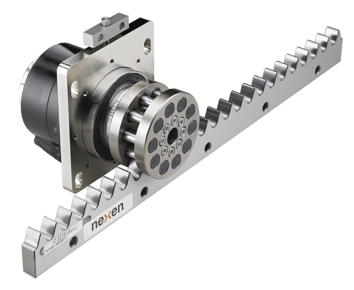
Rack and pinion system
To start designing racks in Fusion, install the Rack Gear Generator by Niklas Pöllönen. Once installed, the Rack Gear option appears under the Create tab in the solids section.
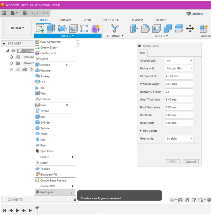
Rack Gear add-in dialog
Once you’ve made a spur gear, go through the following options to make a matching rack:
- Define with: similar to the spur gear’s Module. Set this to Module to match your spur gear; a Module entry will then appear, and you should enter the same module value as your spur gear.
- Pressure angle: must match your spur gear.
- Number of teeth: determines the rack’s length.
- Gear thickness: the thickness of the material below the teeth.
- Root fillet radius: as with the spur gear, set as large as the add-in allows.
- Backlash: best left at
0.15mm. - Base width: corresponds to the spur gear’s Gear thickness. The rack and pinion will be perfectly flush if both values match.
- Gear style: the gear style can change the type from straight to helical to herringbone; the other types are more complex and aren’t covered here.
With spur gears and rack-and-pinion systems, you can add mechanical advantage, change direction, or convert rotation into linear motion in your Rover attachments.